| CATEGORII DOCUMENTE |
| Bulgara | Ceha slovaca | Croata | Engleza | Estona | Finlandeza | Franceza |
| Germana | Italiana | Letona | Lituaniana | Maghiara | Olandeza | Poloneza |
| Sarba | Slovena | Spaniola | Suedeza | Turca | Ucraineana |
Direct Current Motors
1 Introduction
In Chapter 5, we stated that a generator is a machine that converts mechanical energy into electric energy. When a machine converts electric energy into mechanical energy, it is called a motor. There is no fundamental difference in either the construction or the operation of the two machines. In fact, the same machine may be used as a motor or a generator.
There are basically two types of motors: alternating-current (ac) motors and direct-current (dc) motors. An ac motor converts alternating (time-varying) power into mechanical power. When a machine converts time-invariant power into mechanical power, it is said to be a dc motor. This chapter is devoted to the study of dc motors.
When most of the power being generated, transmitted, and consumed is of the ac form, the use of a dc motor requires the installation of extra equipment for converting ac into dc. To justify the additional cost of a commutator on one hand and the installation of ac-to-dc converters on the other, a dc motor is put into service only when its performance is superior to that of an ac motor. By superior performance we simply mean that a dc motor is capable of doing what cannot be easily accomplished with an ac motor. For example, a dc motor can develop starting torque several orders of magnitude higher than a comparable size ac motor. A dc motor can operate at speeds that cannot be attained by an ac motor.
A dc motor is extensively used in control systems as a positioning device because its speed as well as its torque can be precisely controlled over a wide range. A dc motor is, of course, a logical choice when a dc power source is easily available.
The nominal unit to specify the power output of a dc motor is the horsepower (1 hp = 746 W). Direct-current motors are built in sizes ranging from fractional horsepower to over 1000 horsepower. Some of the applications of dc motors include automobiles, boats, airplanes, computers, printers, robots, electric shavers, toys, audio and video cassette recorders, movie cameras, traction motors for railways, subway trains and trams, rolling mills, hoist cranes, punch presses, and forklifts.
2 Operation of a DC Motor
Since there is no difference in construction between a dc generator and a dc motor, the three types of dc generators discussed in Chapter 5 can also be used as dc motors. Therefore, there are three general types of dc motors shunt, series, and compound. The permanent-magnet (PM) motor is a special case of a shunt motor with uniform (constant) flux density. We can also have a separately excited motor if we use an auxiliary source for the field winding. Because it is not practical to employ two power sources, one for the field winding and the other for the armature circuit, a separately excited motor is virtually nonexistent. However, a separately excited motor can also be treated as a special case of a shunt motor.
The principle of operation of a dc motor is explained in detail in Section A coil in an uniform magnetic field.
A brief review is given here. In a dc motor, a uniform magnetic field is created by its poles. The armature conductors are forced to carry current by connecting them to a dc power source (supply) as shown in Figure 1. The current direction in the conductors under each pole is kept the same by the commutator. According to the Lorentz force equation, a current-carrying conductor when placed in a magnetic field experiences a force that tends to move it. This is essentially the principle of operation of a dc motor. All the conductors placed on the periphery of a dc motor are subjected to these forces, as shown in the figure. These forces cause the armature to rotate in the clockwise direction. Therefore, the armature of a dc motor rotates in the direction of the torque developed by the motor. For this reason, the torque developed by the motor is called the driving torque. Note that the torque developed by the conductors placed on the armature of a dc generator is in a direction opposite to its motion. Therefore, it can be labeled the retarding torque.
The magnitude of the average torque developed by these forces must be the same in both machines, since it does not matter whether the current is forced through the armature conductors by an external power source or is the result of the induced emf in the conductors. Thus,
![]() (1)
(1)
where Ka = PZ/ 2p a is the machine constant, Fp is the flux per pole, and Ia is the armature current.
As the armature rotates, each coil on the armature experiences a change in the flux passing through its plane. Therefore, an electromotive force (emf) is induced in each coil. In accordance with Faradays law of induction, the induced emf must oppose the current entering the armature. In other words, the induced emf opposes the applied voltage.
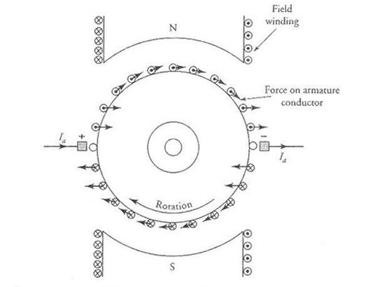
Figure 1 Force experienced by armature conductors in a 2-pole dc motor.
For this reason, we commonly refer to the induced emf in a motor as the back emf or counter emf of the motor.
The average value of the induced emf at the armature terminals should, however, be the same as that for a dc generator because it does not really matter whether the armature is being driven by a prime mover or by its own driving torque. Thus,
![]() (2)
(2)
where wm is the angular velocity of the armature (rad/s).
If R is the effective (total) resistance in the armature circuit and Vs is the applied voltage across the armature terminals, then the armature current is
 (3)
(3)
This equation can also be written as
![]() (4)
(4)
Since the resistance of the armature circuit R is usually very small, the voltage drop across it is also small in comparison with the back emf Ea. Therefore, most of the applied voltage Vs is needed to overcome the back emf Ea. It should also be evident from the above equation that the back emf in the motor is smaller than the applied voltage.
Starting a DC Motor
At the time of starting, the back emf in the motor is zero because the armature is not rotating. For a small value of the armature-circuit resistance R, the starting current in the armature will be extremely high if the rated value of Vs is impressed across the armature terminals. The excessive current can cause permanent damage to the armature windings.
Thus, a dc motor should never be started at its rated voltage.
In order to start a dc motor, an external resistance must be added in series with the armature circuit, as shown in Figure 2 for a PM motor. The external resistance is gradually decreased as the armature comes up to speed. Finally, when the armature has attained its normal speed, the external resistance is cut out of the armature circuit.
Armature Reaction
The theory of commutation and armature reaction as outlined in Chapter 5 for dc generators is also applicable to dc motors. The only differences is that the direction of the current in a conductor under a pole in a dc motor is opposite to that in a generator for the same direction of rotation. Therefore, the field created by the armature current in a dc motor is opposite in direction to that created by the current in the armature of a dc generator. Since the brushes were advanced to secure a good commutation in a dc generator, the brushes should be retreated in a dc motor.
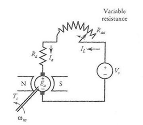
Figure 2 Variable resistance inserted in series with the armature circuit during starting of a dc (PM) motor.
In a dc machine has interpoles, the polarities of the interpoles for the dc motor must be opposite to those of the dc generator. As the interpoles carry armature current and the armature current is already in the opposite direction, the interpole polarities are automatically reversed. The same is true for the compensating windings. Therefore, no action is needed when a dc generator designed with interpoles or compensating windings is used as a dc motor.
3 Speed Regulation
The armature current of a motor increases with load. For a constant applied voltage, the increase in the armature current results in a decrease in the back emf. The reduction in the back emf causes a drop in the speed of the motor. The speed regulation is a measure of the change in speed from no load to full load.
When the change in speed at full load is expressed as a percent of its full-load speed, it is called the percent speed regulation (SR%). In equation form, the percent speed regulation is
 (5)
(5)
where NmnL(wmnL) is the no-load speed, and NmfL(wmfL) is the full-load speed of a dc motor.
As we continue our discussion of dc motors, we will observe that:
(a) a series motor is a variable-speed motor because its speed regulation is very
high, (b) a shunt motor is essentially a constant-speed motor because its speed regulation is very small, and (c) a compound motor is a variable-speed motor because its speed regulation is higher than that of the shunt motor.
4 Losses in a DC Motor
The power input to a dc motor is electrical and the power output is mechanical. The difference between the power input and the power output is the power loss. A dc motor portrays the same power losses as a dc generator.
When the power is supplied to a motor, a significant portion of that power is dissipated by the resistances of the armature and the field windings as copper loss. The remainder power (the developed power) is converted by the motor into mechanical power. A part of the developed power is consumed by the rotational loss. The difference is the net mechanical power available at the shaft of the motor. A typical power-flow diagram of a dc motor is shown in Figure 3.
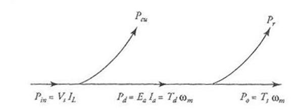
Figure 3 A typical power-flow diagram of a dc motor.
5 A series Motor
In a series motor the field winding is connected in series with the armature circuit as shown in Figure 4. We have also included an external resistance Rax in series with the armature that can be used either to start the motor and then be shorted or to control the speed of the motor. Since the series field winding carries the rated armature current of the motor, it has few turns of heavy wire. As the armature current changes with the load, so does the flux produced by the field winding. In other words, the flux set up by a series motor is a function of the armature current. If the flux per pole can be expressed as
![]() (6)
(6)
then the back emf is
![]() (7)
(7)
and the torque developed by the series motor is
![]() (8)
(8)
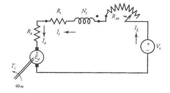
Figure 4 An equivalent circuit of a series motor with a variable starting resistance.
From the above equations, it is evident that the back emf in the motor is proportional to the armature current, and the torque developed by a series motor is proportional to the square of the armature current as long as the motor is operating in the linear region. As the armature current increases, so does the flux produced by it. An increase in the flux enhances the level of saturation in the motor. When the motor is saturated, the flux increases only gradually with further increase in the armature current. Hence, the torque developed is no longer proportional to the square of the current. The torque versus armature current characteristic of a series motor is given in Figure 5.
When a series motor operates under no load, the torque developed by the motor is just sufficient to overcome the rotational loss in the machine. Since the rotational loss is only a fraction of the full-load torque, the torque developed by the machine is very small at no load. From Eq. (8), the armature current must also be very small. Therefore, the back emf at no load must be nearly equal to the applied voltage Vs. Since the back emf is also proportional to the armature current and the armature current is a small fraction of its rated value, the motor must attain a relatively high speed. In fact, it is possible for a series motor to self-destruct under no load owing to centrifugal action.
As we load the motor, the torque developed by it must increase. The increase in the torque necessitates an increase in the armature current. The increase in the armature current causes an increase in the voltage drop across the armature-circuit resistance, the field-winding resistance, and the external resistance. For a fixed applied voltage, the back emf must decrease with load. Since the back emf is also proportional to the armature current, the speed of the motor must drop. Figure 6 shows the torque-speed characteristic of a series motor. We will comment on the nature of the curve shortly. Also shown in the figure is the power developed by a series motor as a function of its speed.
From the equivalent circuit of Figure 4, we have
![]()
where R = Ra + Rs + Rax is the total armature-circuit resistance. Substituting for Ea from Eq. (7), we can obtain an expression for the speed of the motor in terms of armature current as
 (9)
(9)
This equation states that the speed of a series motor is practically inversely proportional to the armature current. The nature of the speed-current characteristic is depicted in Figure 5.
Equation (9) can also be rewritten as
 (10)
(10)
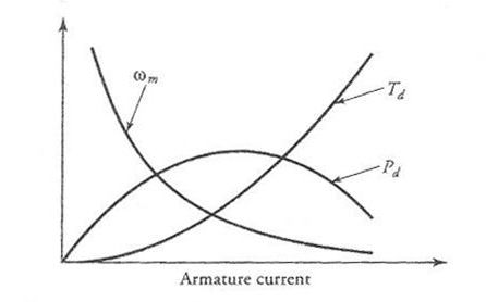
Figure 5 Torque developed, power developed, and speed characteristics of a series motor as a function of armature current.
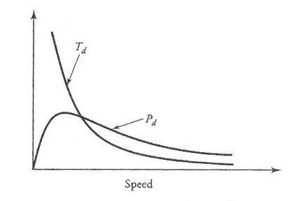
Figure 6 Torque and power developed characteristics of a series motor as a function of speed.
The torque developed, from Eq. (8), can now be expressed as
 (11)
(11)
From this equation it is evident that, for all practical purposes, the torque developed by a series motor is inversely proportional to the square of its speed. The nature of the speed-torque characteristic in Figure 6 should now be obvious. A series motor provides high torque at low speed and low torque at high speed. For this reason, a series motor is suitable for hoists, cranes, electric trains, and a host of other applications that require large starting torques.
Since the torque developed by a series motor is also proportional to the square of the applied voltage, the torque developed by it can be controlled by controlling the applied voltage. For example, at a given speed, doubling the applied voltage results in quadrupling of the torque.
The power developed by a series motor is
![]()
The power developed by a series motor for a constant applied voltage is maximum when Ia Iam and dPd /dIa 0. Thus, differentiating the above equation with respect to Ia and setting it to zero, we obtain

The maximum power developed by a series motor is

For a stable operation, the
operating range of a series motor is well below maximum power developed by it.
The power (and the torque developed) as a function of armature current are shown in Figure 5.![]()
6 A Shunt Motor
The equivalent circuit of a shunt motor is shown in Figure 8 with a starting resistor in the armature circuit. The field winding is connected directly across the source. For a constant-source voltage, the flux created by the field winding is constant. The torque developed by the motor is
![]() (14)
(14)
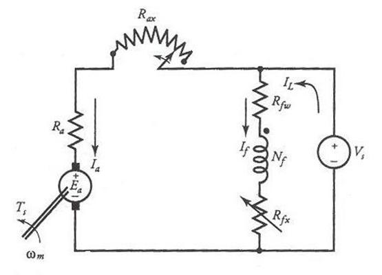
Figure 8 An equivalent circuit of a shunt motor with a starting resistor in the armature circuit.
Where K = KaFp is a constant quantity. Hence the torque developed by a shunt motor is proportional to the armature current as shown in Figure 9.
When the shunt motor is driving a certain load, the back emf of the motor is
![]() (15)
(15)
Since Ea = KaFpwm, the operating angular velocity (speed) of the motor is
 (16)
(16)
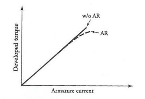
Figure 9 Torque developed by a shunt motor as a function of armature current with armature reaction (AR) and without armature reaction (w/o AR)
Although we are developing relationships in terms of the angular velocity wm, we still refer to it as the speed of the motor.
When the load on the motor is increased, the following sequence of events takes place:
(a) The armature current Ia increases to satisfy the demand of increased
load.
(b) The voltage drop across the armature circuit resistance Ra increases.
(c) For a fixed-source voltage, the back emf Ea decreases.
(d) Since the flux is constant when armature reaction is negligible, the
decrease in the back emf of the motor is accompanied by a decrease in
its speed as shown in Figure 10 (curve d).
With the increase in the armature current, the armature reaction becomes more significant if the motor is not compensated for it.
The increase in the armature reaction decreases the flux in the motor, which, in turn, causes an increase in the speed. Depending upon the magnetic saturation of the motor and the severity of the armature reaction, the increase in the speed due to the armature reaction may be less than, equal to, or greater than the drop in the speed due to the increase in the armature current, as depicted in Figure 10 by curves a, b, and c, respectively. Curve c is not really desirable, as it may lead to instability of operation. We can overcome this undesirable effect by adding few series turns in the motor. Such a winding, when included as a part of a shunt motor, is called the stabilizing winding.
Equation (16) can also be written as
 (17)
(17)
where wmnL = Vs/KaFp is the no-load speed of the motor. This is the speed at which the torque developed by the motor is zero.
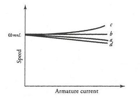
Figure 10 Speed versus armature current characteristic of a shunt motor.
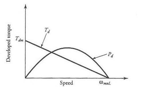
Figure 11 Torque developed and power developed as a function of speed of a typical shunt motor.
The actual speed of the motor is bound to be lower than wmnL owing to the rotational loss. As Ra 0, the speed of a shunt motor wm wmnL. In other words, a shunt motor is basically a constant-speed motor.
We can also obtain an expression for the torque developed in terms of the speed of the motor from Eqs. (14) and (16) as
 (18)
(18)
This straight-line relationship, depicted in Figure 11, is the torque-speed characteristic of a shunt motor. It simply states that the speed increases as the load on the motor decreases. Also plotted in Figure 11 is the power developed by the machine as a function of its speed. We can show that the power developed by a shunt motor is maximum when its speed is equal to 0.5 wmnL. The corresponding expression for the maximum power developed by the machine is
 (19)
(19)
7 The Compound Motor
A shunt motor may have an additional series field winding in the same manner as a shunt generator. The series field winding may be connected so that the flux produced by it aids the flux set up by the shunt field winding, in which case the motor is said to be a cumulative compound motor. A motor is said to be differential compound when the flux of the series field winding opposes the flux of the shunt field winding. In fact, the stabilizing winding discussed in the previous section makes a shunt motor to behave like a cumulative compound motor.
A compound motor may be connected either as a short-shunt motor or a long-shunt motor. In a long-shunt motor, the shunt field winding is directly connected across the power source as depicted in Figure 13b. Therefore, the flux created by the shunt field winding is constant under all loading conditions. On the other hand, the shunt field winding of a short-shunt compound motor is connected directly across the armature terminals as shown in Figure 13a. The flux created by the shunt field winding of a short-shunt motor decreases (somewhat) with an increase in the load owing to the voltage drop across the series field winding.
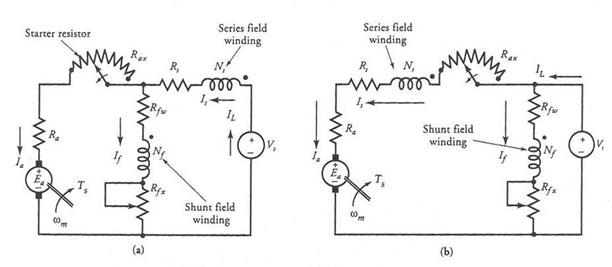
Figure 13 (a) A short-shunt and (b) a long-shunt compound motor.
As you may have guessed, the characteristics of a compound motor are a combination of the characteristics of a shunt motor and a series motor. As we increase the load on a compound motor, the following sequence of events takes place:
The total flux (increases/decreases) owing to the increase in the series-winding current for a (cumulative/differential) compound motor. That is,
![]() (20)
(20)
where Fp is the total flux in the motor, Fsh is the flux due to the shunt field winding, and kfIa is the flux produced by the series field winding. Note that the minus sign is for the differential compound motor.
The (increase/decrease) in the flux with an increase in the armature current causes the torque to (increase/decrease) at a faster rate in a (cumulative/differential) compound motor than in a shunt motor. This is based on the fact that the torque developed by a compound motor is
![]() (21)
(21)
The torque versus armature current characteristics of cumulative and differential compound motors are shown in Figure 14.
The (increase/decrease) in the flux accompanied by an increase in the voltage drops across the armature circuit and the series field-winding resistance causes the motor speed to (decrease/increase) more rapidly than it does in a shunt motor. This is so because the motor speed is
 (22)
(22)
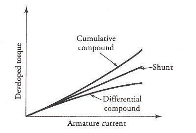
Figure 14 Torque-current characteristics of shunt, cumulative compound, and differential compound motors.
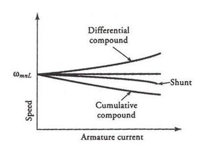
Figure 15 Speed-current characteristics of shunt, cumulative compound, and differential compound motors.
The speed versus armature current characteristics of cumulative and differential compound motors are given in Figure 15.
In a differentially compound motor, the flux decreases with an increase in the armature current. Therefore, there is a possibility for a differentially compound motor to attain dangerously high speed as the flux due to the series field winding approaches the flux created by the shunt field winding.
A cumulative compound motor has a definite no-load speed, so it does not run away like a series motor when the load is removed. It also develops high starting torque when the load is suddenly increased. This makes it suitable for such applications as rolling mills, shears, and punching presses. It is also a preferred motor for applications (such as cranes and elevators) that (a) require high starting torque, (b) are prone to sudden load changes, and (c) present a possibility of going from full load to no load.
8 Methods of Speed Control
The foremost reason that a dc motor is used extensively in the design of a control system is the ease with which its performance can be tailored to meet the demands of the system. Stated differently, a dc motor enables us to change its speed at any desired torque without making any changes in its construction.
The two methods that are commonly used to secure speed control are armature resistance control and field control.
Armature Resistance Control
In this method, the speed control is achieved by inserting a resistance Rc in the armature circuit of a shunt, series, or compound motor as illustrated in Figure 1 In a shunt or a compound motor, the field winding is connected directly across the full-line voltage. The additional resistance in the armature circuit decreases the back emf in the motor for any desired armature current. Since the flux in the motor is constant and the torque depends upon the armature current, the decrease in the back emf forces a drop in the motor speed.
We can express the speed of a dc motor in terms of its armature current as
 (23)
(23)
where
![]()
for a series or a compound motor, and
![]()
for a shunt motor.
It is obvious from the above equation that any increase in the value of the control resistance Rc decreases the speed of the motor. The armature resistance control method, therefore, is suitable to operate the motor at a speed lower than its rated speed while delivering the same torque. The speed-torque characteristics of series, shunt, and compound motors for various values of the control resistor are depicted in Figure 17. In fact, the starting resistors, as we have shown in the equivalent circuits of dc motors, can also be used for speed-control purposes.
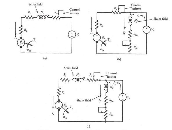
Figure 16 Armature resistance control for (a) series motor, (b) shunt motor, and (c) compound motors.
The disadvantages of this method of speed control are the following:
(a) A considerable power loss in the control resistance Rc
(b) A loss in the efficiency of the motor
(c) Poor speed regulation for the shunt and the compound motors
The armature resistance control method is essentially based upon the reduction in the applied voltage across the armature terminals of a dc motor. Therefore, it should be possible to control the speed of a dc motor by simply connecting its armature to a variable voltage source. This method of speed control is known as the Ward-Leonard method and is discussed in the next section.
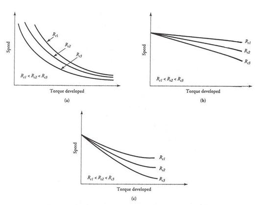
Figure 17 Speed-torque characteristics of (a) series, (b) shunt, (c) compound motors showing the effect of additional resistance in the armature circuit.
Field-Control Method
Another approach to control the speed of a dc motor involves the control of the field current, which in turn controls the flux in the motor. The field current in a shunt motor can be controlled by inserting an external resistor in series with the field winding. Because the field current is a very small fraction of the total current intake of a shunt motor, the power dissipated by the external resistor is relatively small. Therefore, the flux-control method is economically better than the armature-resistance-control method.
To control the flux in a series motor, a field diverter resistor can be connected in parallel with the series field winding. If all the coils in a series field winding are connected in series, we can also change the flux in a series motor by connecting the coils in parallel.
The addition of a resistance in series with the shunt field winding or in parallel with the series field winding causes the field current and thereby the flux
in the motor to decrease. Since the speed of a motor is inversely proportional to its flux, a decrease in its flux results in an increase in its speed.
Thus, the flux-control method makes a motor operate at a speed higher than its rated speed.
As the torque developed by a shunt motor is proportional to the product of the armature current and the flux per pole, a decrease in the flux must be accompanied by a corresponding increase in the armature current for the motor to deliver the same torque. This method of speed control is, therefore, not satisfactory for compound motors, because any decrease in the flux produced by the shunt field winding is offset by an increase in the flux produced by the series field winding owing to an increase in the armature current.
9 The Ward-Leonard System
A critical examination of the armature-resistance-control method reveals that the insertion of an external resistor in series with the armature circuit is equivalent to applying a voltage lower than the rated across the armature terminals. It should, therefore, be obvious that we can achieve the same effect by actually applying a reduced voltage across the armature terminals of a dc motor while the voltage across the shunt field winding of a shunt or a compound motor is held constant. This method of speed control is known as the armature voltage control. The advantage of this method is that it eliminates the excessive power loss that is inherently associated with the armature resistance control. The main drawback is that it requires two power sources to control the speed of a shunt or a compound motor.
The Ward-Leonard system of speed control is, in fact, based upon the method of armature voltage control. To control the speed of a dc motor, this system requires two generators and an ac motor. The three-phase ac motor acts as a prime mover that drives both generators as illustrated in Figure 18. One generator, called the exciter, provides a constant voltage that is impressed upon the field windings of the other separately excited generator and the separately excited motor under control as shown. The armature winding of the motor is permanently connected to the armature terminals of the other generator, whose voltage can be varied by varying its field current. The variable armature voltage provides the means by which the motor speed can be controlled.
The motor speed is high when the generator voltage is high. For the generator voltage to be high, the total resistance in its field circuit must be low. On the other hand, a high resistance in the field circuit of the generator results in low generator voltage and thereby low motor speed. In other words, by simply controlling the field-winding current of the dc generator, we can achieve an unlimited speed control of a dc motor.
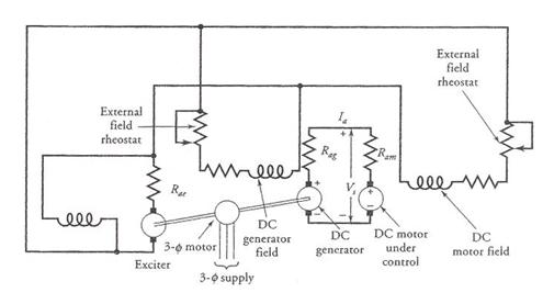
Figure 18 A Ward-Leonard system of speed control.
It must be obvious that we need a set of three machines to control the speed of a dc motor. The system is expensive but is used where an unusually wide and very sensitive speed control is desired. This arrangement offers an excellent step-less speed control and is well suited for such applications as passenger elevators, colliery winders, and electric excavators, to name just a few.
10 Torque Measurement
The two methods that are commonly used to measure the torque of a dc motor are the prony brake test and the dynamometer test.
Prony Brake Test
The most common method to measure the torque and the efficiency of a motor is called the prony brake test. The basic arrangement of the test is shown in Figure 19. In this method, a pulley is mounted on the shaft of the motor that acts as a brake drum. A brake band with or without brake blocks is wrapped around the brake drum as shown. One end of the brake band may be permanently fastened to the torque arm, and the other end can be adjusted by a thumbscrew for tightening against the surface of the brake drum. For high-horsepower motors, cooling of the brake drum may be necessary.
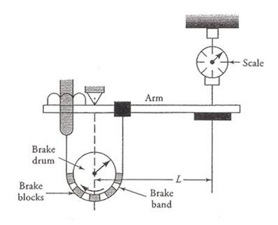
Figure 19 The prony brake test.
The brake band is slowly tightened until the motor runs at its rated speed. The tendency of the torque arm to move with the drum is resisted by the force of the spring (scale) attached at the far end of the torque arm. The deflection of the spring may be calibrated in terms of either force units or torque units. If the calibration is done to display the force, the torque is simply the product of the force times the effective length of the torque arm. The effective length is simply the distance between the center of the pulley and the place where the spring is attached.
In our discussion we have assumed that the torque arm is perfectly horizontal before the beginning of the test and the dead (tare) weight of the arm is zero. In actual practice, the dead weight of the torque arm must be taken into consideration, as illustrated by the following example.
Dynamometer Method
The drawbacks of the prony brake test are the vibrations caused by the brake blocks and the necessity of constantly cooling the brake drum. These drawbacks are overcome by a torque-measuring electrical device known as the dynamometer. A dynamometer is a dc machine with a separately excited field winding.
The only difference between a dc motor and a dynamometer is that the stator of the dynamometer is also free to rotate, whereas it is rigid in a dc motor. The machine is mounted on low-friction ball bearings. On the outside of the stator of a dynamometer is fastened a torque arm, the other side of which is attached to a spring (scale) as shown in Figure 21.
The armature of the dynamometer is rotated by coupling it to the shaft of the motor under test. The rotation of the armature coils in a uniform magnetic field results in an induced emf in them (generator action). If the armature circuit is completed by connecting the armature coils to a resistive load, a current will flow in the armature winding. The magnitude of the current depends upon the induced emf and the load resistance. The current-carrying conductors in a uniform magnetic field now experience a force acting on them (motor action). The direction of the force is such that it tends to resist the rotation of the armature. Because the stator, which houses the field windings, is free to rotate, it is pulled around equally by the motor action. The only restraining force acting on the stator is provided by the spring, very much like the prony brake test. By controlling the flux in the motor, we can control the speed of the motor and make it run at any desired speed.
A 5-hp motor rated at 1200 rpm is tested on a dynamometer whose torque arm is 40 cm in length.
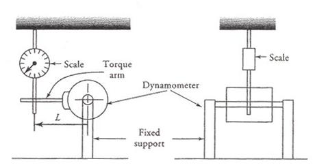
Figure 21 A dynamometer arrangement to test a dc motor.
11 Braking or Reversing DC Motors
In certain applications, it may be necessary to either stop the motor quickly or reverse its direction of rotation. The motor may be stopped by using frictional braking. The drawbacks of frictional braking are that the operation is (a) difficult to control, (b) dependent upon the braking surface, and (c) far from being smooth.
Therefore, it is desirable to use other means of stopping and/or reversing the direction of rotation of a dc motor. The three commonly employed methods are plugging, dynamic braking, and regenerative braking.
Plugging
Stopping and/or reversing the direction of a dc motor merely by reversing the supply connections to the armature terminals is known as plugging or counter-current braking. The field-winding connections for shunt motors are left undisturbed. This method is employed to control the dc motors used in elevators, rolling mills, printing presses, and machine tools, to name just a few.
Just prior to plugging, the back emf in the motor is opposing the applied source voltage. Because the armature resistance is usually very small, the back emf is almost equal and opposite to the applied voltage. At the instant the motor is plugged, the back emf and the applied voltage are in the same direction. Thus, the total voltage in the armature circuit is almost twice as much as the applied voltage. To protect the motor from a sudden increase in the armature current, an external resistance must be added in series with the armature circuit. The circuit connections, in their simplest forms, for shunt and series motors are given in Figure 22.
As the current in the armature winding reverses direction, it produces a force that tends to rotate the armature in a direction opposite to its initial rotation. This causes the motor to slow down, stop, and then pick up speed in the opposite direction. Plugging, therefore, allows us to reverse the direction of rotation of a motor. This technique can also be used to brake the motor by simply disconnecting the power from the motor when it comes to rest. As a further safeguard, mechanical brakes can also be applied when the motor is coming to rest.
At any time during the plugging action, the armature current is
 (25)
(25)
Thus, the braking torque is
![]() (26)
(26)
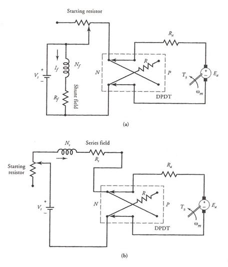
Figure 22 Plugging of (a) a shunt motor and (b) a series motor.
where
 and
and 
For the series motor, the flux also depends upon the armature current, which in turn depends upon the motor speed. Since the flux in a shunt motor is constant, the above equation, for a shunt motor, becomes
![]() (27)
(27)
where
![]() and
and 
From the above equation, it is obvious that even when a shunt motor is reaching zero speed, there is some braking torque, Tb = K3. If the supply voltage is not disconnected at the instant the motor reaches zero speed, it will accelerate in the reverse direction.
Dynamic Braking
If the armature winding of a dc motor is suddenly disconnected from the source, the motor will coast to a stop. The time taken by the motor to come to rest depends upon the kinetic energy stored in the rotating system.
Dynamic braking, on the other hand, makes use of the back emf in the motor in order to stop it quickly. If the armature winding, after being disconnected from the source, is connected across a variable resistance R, the back emf will produce a current in the reverse direction. A current in the reverse direction in the armature winding results in a torque that opposes the rotation and forces the motor to come to a halt.
The dynamic braking effect is controlled by varying R. At the time of dynamic braking, R is selected to limit the inrush of armature current to about 150% of its rated value. As the motor speed falls, so does the induced emf and the current through R. Thus, the dynamic braking action is maximum at first and diminishes to zero as the motor comes to a stop. Simple circuits illustrating the principle of dynamic braking for a shunt and a series motor are given in Figure 23.
At any time during the dynamic braking process, the armature current is
and the braking torque is
 (28)
(28)
Since the flux in a series motor is proportional to the armature current, Fp = kfIa, the braking torque for a series motor becomes
![]() (29)
(29)
Figure 23 Dynamic braking of (a) a shunt motor and (b) a series motor.
On the other hand, the braking torque for a shunt motor is
![]() (30)
(30)
From Eqs. (28), (29), and (30), it is evident that the braking torque vanishes as the motor speed approaches zero.
Regenerative Braking
Regenerative braking is used in applications in which the motor speed is likely to increase from its rated value. Such application include electric trains, elevators, cranes, and hoists. Under normal operation of a dc motor, say a permanent-magnet (PM) motor in an electric train, the back emf is slightly less than the applied voltage. Note that the back emf in a PM motor is directly proportional to the motor speed. Now assume that the train is going downhill. As the motor speed increases, so does the back emf in the motor. If the back emf becomes higher than the applied voltage, the current in the armature winding reverses its direction and the motor becomes a generator. It sends power back to the source and/or other devices operating from the same source. The reversal of armature current produces a torque in a direction opposite to the motor speed.
Consequently, the motor speed falls until the back emf in the motor is less than the applied voltage. The regenerative action not only controls the speed of the motor but also develops power that may be used elsewhere.
S U M M A R Y
We devoted this chapter to the study of dc motors. Even though dc motors are not used as widely as ac motors, they do have excellent speed-torque characteristics that cannot be duplicated by ac motors. They also offer more flexible and precise speed control than their ac counterparts.
The principle of operation of a dc motor is no different from that of a dc generator. The induced emf in a dc motor opposes the applied voltage and for this reason is called the back emf. The back emf of the motor adjusts itself depending upon the torque requirements of the load. Because the back emf is zero at the instant of starting a motor, a dc motor should never be started by applying a rated voltage across the armature terminals. We must either use a variable voltage or insert a variable resistance in the armature circuit at the time of starting.
As the load on the motor changes, so does its speed. Therefore, we defined the percent speed regulation of a dc motor as

During our discussion of dc motors, we observed that a series motor is a variable-speed motor while a shunt motor is essentially a constant-speed motor. Since the speed regulation of a compound motor is higher than that of a shunt motor, it is also considered a variable-speed motor.
A shunt motor is used in such applications as a grinders, polishers, wood planers, and washing machines. Its speed can be adjusted by employing (a) field control, (b) armature control, and (c) variable voltage control techniques. An adjustable-speed shunt motor may be found in such applications as lather, elevators, large blowers, and small printing presses.
A series motor is used in applications such as cranes, turntables, bucket hoists, continuous conveyers, and mine hoists. Its speed can be controlled by using the same techniques mentioned for the shunt motor.
A compound motor is used in compressors, rotary presses, punch presses, elevators, and stamping machines. Field-control and armature-control methods can also be used to control its speed.
The Ward-Leonard method of speed control, although expensive, is employed where an unusually wide and very sensitive speed control is required. It is the system of choice for the regenerative braking process.
We described two methods of testing dc motors, the prony brake test and the dynamometer method. The rope test is a slight variation of the prony brake test. Shunt and compound motors can also be tested by running them at no load. The power input to these machines under no load yields information on the rotational losses.
In order to stop and/or reverse the direction of rotation of a dc motor, we employ such methods as plugging, dynamic braking, and regenerative braking. Each of these techniques is based upon temporarily converting a motor into a generator. The retarding torque of the generator then acts as a brake on the machine.
The plugging technique requires reversal of the supply across the armature terminals. The dynamic braking method involves the connection of a suitable resistance across the armature terminals when the supply is disconnected. When the armature current is fed back to the supply, the braking technique is said to be regenerative. For regenerative braking, the induced emf in the motor must be greater than the line voltage.
|
Politica de confidentialitate | Termeni si conditii de utilizare |

Vizualizari: 5039
Importanta: ![]()
Termeni si conditii de utilizare | Contact
© SCRIGROUP 2025 . All rights reserved