| CATEGORII DOCUMENTE |
| Bulgara | Ceha slovaca | Croata | Engleza | Estona | Finlandeza | Franceza |
| Germana | Italiana | Letona | Lituaniana | Maghiara | Olandeza | Poloneza |
| Sarba | Slovena | Spaniola | Suedeza | Turca | Ucraineana |
The atomization of fuel into the air charge is extremely significant to the functioning of the internal combustion engine. If any single aspect of engine performance can be labeled 'most important,' fuel control is a strong candidate for the honor. Electronic fuel injection, in particular, can do that job better than any other form of fuel injection or fuel mixing device. Principles, applications, and modification of EFI will be dealt with in the discussion that follows. Neither cis ('continuous injection system'), a type of fuel injection that uses pneumatic and hydraulic controls, nor throttle-body fuel injection is discussed in this book. EFI has proven its superiority all the way from economy shoebox-es to Indy champ cars. It has been a long time since a major road race winner was equipped with a fuel system other than EFI. Surely, then, any serious turbo will be accompanied by EFI. Nothing else even comes close. Start with the best there is, and you won't wind up stuck or cornered later on.
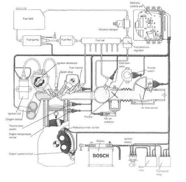
Fig. 7-1. The modern engine-management system.
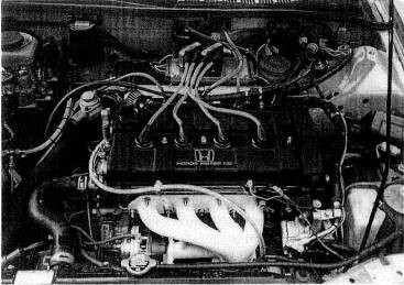
Fig. 7-2. An adaptation of the Electromotive TEC II EFI to an ultramodern engine in the Acura Integra.
An EFI system is composed of electrically actuated fuel valves that open by a voltage signal, permitting fuel to flow. The air/fuel ratio is controlled by the amount of time the injectors are held open per combustion cycle. This is called pulse duration. The EFI computer gathers data from a group of sensors that tell it how fast the engine is running and the load at that instant. With that data, the computer starts looking through its stored information to find how long it should hold the injectors open to satisfy the fuel requirements dictated by those load conditions. When that information is found, it is pulled out of the memory and relayed to the injectors as a voltage pulse of a specific duration. These durations are measured in thousandths of a second, or milliseconds (msec). When that cycle is complete, the programming of the computer tells it to go do it all over again but to be alert for new conditions. All this data acquisition, analysis, and distribution takes about 15% of the computer's attention. The remainder of the time it just sits. Too bad it can't be reconciling your checkbook in its off hours. The sensors the computer relies on to keep it informed are an integral part of EFI and are analogous to the eyes and ears of the system:
Air-mass/airflow sensor. An EFI system configured with an air-mass or airflow sensor is called a 'mass flow' EFI system. The sensor attempts to measure the number of air molecules flowing through the system at any instant. If this number is divided by the speed of the engine, it gives an accurate reflection of the amount of fuel needed per combustion putt in the engine.
Air temperature sensor. Air density changes as a function of temperature. Therefore, the computer must know to change the pulse durations slightly if the air temperature sensor detects a change in the air temperature.
Barometric sensor. Air density also changes with altitude. An atmospheric pressure sensora barometerprovides the computer a varying signal with changes in altitude.
Coolant temperature sensor. The amount of fuel the engine needs is inversely proportional to engine temperature. The coolant temperature sensor reflects the engine's operating temperature. With a cold engine, a huge amount of fuel is required just to get enough to vaporize, so it can burn. The hotter the engine, the easier vaporization becomes, and the less fuel required.
Manifold vacuum/pressure sensor. Not all EFI systems will be equipped with a manifold pressure sensor. Those that are, are properly called ''speed density' EFI systems. When the manifold absolute pressure (MAP) sensor is used, an air- mass sensor or airflow meter is not necessary. The manifold vacuum or manifold pressure at any given instant is a good reflection of the engine load at that time. Hence, the MAP sensor provides the computer with another bit of operating condition data.
Oxygen sensor. The oxygen sensor measures the amount of oxygen left over from the combustion process. It is mounted in the exhaust manifold and thus becomes the after-the-fact watchdog for the computer. If the sensor detects too much oxygen, the computer will know by referring to its stored information that it is time to lengthen the injection pulses slightly, thus adding fuel and using some of the excess oxygen. By monitoring the leftover oxygen, the computer can continuously home the pulse durations in on the air/fuel ratio it was programmed to give. The oxygen sensor's purpose in life is to keep the air/fuel ratio in the ranges needed by the three-way catalytic converter. It is not a power or economy device.
Tachometer circuit. The pulsing of the injectors every combustion cycle must, of course, always be referenced to the engine speed. The tach circuit does this by monitoring the low-voltage pulses to the coil.
Throttle position sensor. The actual output of an engine is largely dependent upon throttle position. Full throttle is obviously asking for everything the engine has, and fuel flow must rise to the occasion. Therefore, throttle position becomes a significant bit of data for the computer. A further data input that the throttle-position sensor offers is the rate of change of the throttle position. This function becomes the equivalent of an accelerator pump in a carburetor. The accelerator pump offers a sudden rich condition to allow a smoother load transition.
Support pieces for the EFI system are fuel pumps, fuel pressure regulators, fuel lines, air valves, idle controls, and relays.
A good working knowledge of EFI must include an understanding of how injector sizes vary with differing requirements of cylinder size, power output, and operating range of manifold pressure. First it is necessary to understand the intrinsic nature of the timed injector and the available time in which it must work. The available time is limited to the time required for one complete engine cycle. In a four-stroke-cycle engine, available injector time is the time required to complete two revolutions of the engine. As the speed of the engine increases, available injector time decreases. Thus the injector inherently takes up a greater and greater portion of the available time as the engine speeds up. Eventually, the point arrives at which engine cycle time is equal to the time the injector needs to deliver the required amount of fuel. This point is the 100% duty cycle point.
Two types of EFI systems are available: sequential and nonsequential. Sequential, which is the most common, pulses an injector in the same order as the firing order of the engine. In so doing, sequential pulses each injector every other revolution; that is, once per engine cycle. The nonsequential style usually pulses all the injectors at the same time and on every revolution.
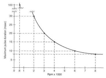
Fig. 7-3. Maximum fuel injection pulse time available per revolution is a function of engine rpm.
EFI therefore has a pulse duration twice as long as non sequential, but nonsequential pulses twice per engine cycle, thereby closely approximating delivery of sequential EFI. A clever variation on sequential injection is the ability to adjust exactly when the pulse occurs relative to the opening of the intake valve.
The two convenient points to remember are at 600 rpm and 6000 rpm. These two points take 100 msec and 10 msec, respectively, per revolution, or 200 msec and 20 msec for complete engine cycles. Again, it is important to remember that 20 msec total time available, whether it is in two pulses of nonsequential EFI or one pulse of sequential EFI. The fundamental idea behind all this analysis stuff is that the injector must be big enough to deliver all the fuel the cylinder requires in 20 msec at 6000 rpm (or even less if the engine runs faster).
Within the scope of low-boost-pressure (under 7 psi) turbo systems added to normally aspirated engines, adequate fuel deliveries can be achieved with modification to the stock EFI equipment. The basic requirement of knowing that the fuel delivered through the injector nozzle is the right amount for the conditions still exists and must be satisfied. Increasing fuel flow through the EFT system is limited to one of three choices:
lengthening injector pulse duration
increasing nozzle size
increasing fuel pressure
Lengthening injector pulse duration. Prior to any attempt to increase fuel flow by longer pulse duration, it is necessary to determine the time of an engine revolution at redline (peak horsepower) and the maximum duration of an injector pulse. This will allow us to calculate whether additional time is avail-able to lengthen pulse duration. Injector pulse duration can be determined by an oscilloscope or pulse duration meter. This measurement must be taken while the car is moving at full throttle near the torque peak, which is approximately two-thirds of redline rpm.
As rpm increases from about 3000 rpm and injectors are open a larger percentage of each revolution, sequential EFI reverts to nonsequential. The distinction between the two types can therefore be ignored in calculating additional fuel flow as long as pulse duration is checked above 4000 rpm. Then it is accurate to analyze available pulse increase based on one pulse per revolution.
The time required for one revolution at engine redline determines whether time is available for longer EFI pulses. This can be obtained from figure 7-3 or by calculation:

Example:
Let redline rpm = 5500.
Then

Once the time of one revolution at the redline is known and redline pulse duration has been measured, the available increase can be calculated. In msec,
![]()
As a percentage,
![]()
Example 1:
Let redline rpm = 5500 and redline pulse duration = 6.2 msec.
Then
Available increase = 10,9 msec - 6.2 msec =4,7 msec
As a percentage,
![]() = 0.758 = 75.8%
= 0.758 = 75.8%
Example 2:
Let redline rpm = 7500 and redline pulse duration = 8.0 msec.

Available increase =8,0 msec - 8,0 msec = 0
In this example, redline pulse duration takes up all the available time at the redline rpm; therefore, no increase is available.
If investigation shows an increase in injector pulse duration is available, then the methods of extending those pulses can be examined:
Sensor signal alteration. Pulse durations can be extended by increasing the resistance in the coolant temperature sensor circuit. The amount of resistance is determined by trial and error. The resistance must be added in increments and only when under boost. This requires a messy series of potentiometers and switches and will always prove less than acceptable.
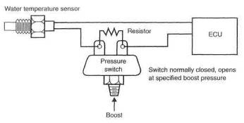
Fig, 7-4. The coolant-temperature-signal-change-based fuel system. Note: This is not a workable fuel system.
Reprogrammed computer chip. Too many problems exist to expect a chip change to offer a means of supplying additional fuel flow. This method is tough to work out on flapper-door-style flowmeters, for example. It will not work on a speed density system unless the MAP sensor is designed to operate at pressures above atmospheric. The tuner with the knowledge to decode an OEM computer program and the equipment to reprogram the system can do the job. These guys are real sharp and real scarce. All in all, this is a tough job to carry out.
Pulse signal interceptor. Currently, the only viable means of extending an injector pulse is to intercept it, modify it based on manifold pressure conditions, and send it on to the injector in place of the original pulse. Good technology and lots of experience are required for success with this approach. Such devices exist in limited applications.
Increasing nozzle size. A change in nozzle size creates a situation wherein, if left alone, the EFI will deliver more fuel all the time under all conditions.
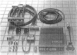
Fig. 7-5. The HKS piggyback computer is designed to operate a factory turbo car at higher-than-stock boost pressures.
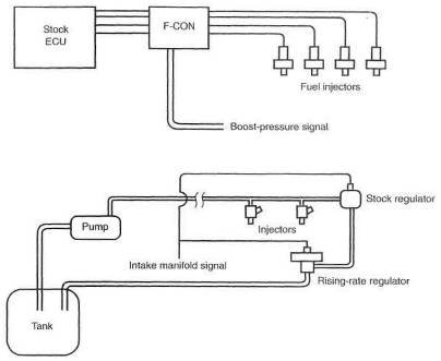
Fig. 7-6. The F-CON computer alters the EFI signal based on the magnitude of the boost-pressure signal.
Fig. 7-7. Rising-rate regulator installed in a fuel system
This is not acceptable; thus, a means of returning fuel flow to its original level at low speeds is necessary. It is possible to do this either by modifying the airflow meter's signal to the ECU or, with flapper-door-style flowmeters, by increasing the return spring tension. The latter done inside the flowmeter and is relatively easy. Injector nozzles up to 50% bigger can usually be retuned to good low-speed operation by either method.
Increasing fuel pressure or adding injectors is only practical up to about 9-10 psi (boost pressure), after which larger injectors become necessary Although OEM ECUs are difficult to reprogram, aftermarket units, which come with software and instructions, are a cinch.
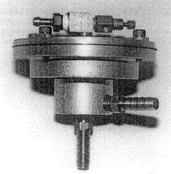
Fig. 7-8. The rising-rate fuel pressure regulator, invented by Ron Nash in the mid-'70s, raises fuel pressure rapidly as boost increases.
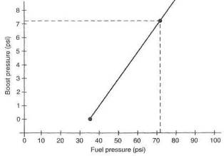
Fig. 7-9. The rising-rate regulator can deliver significantly higher fuel pressures as a function of boost pressure.
With such units, increasing injector size becomes the most potent method of supplying additional fuel. When boost pressure exceeding 9-10 psi is planned, a change of injectors is necessary.
Increasing system fuel pressure as a function of boost pressure is a viable method of increasing fuel flow to accommodate boost pressures up to about 9 psi. Fuel flow changes through a nozzle are proportional to the square root of the pressure change across the nozzle. A boost-pressure-powered fuel pressure regulator can be made to drive the fuel pressure up rapidly to keep pace with rising boost pressure. This type of mechanism is able to use the original injectors but is limited to fuel pressure available through the stock pump. Bosch or other high-pressure EFI fuel pumps can be substituted or used as supplementary pumps. These pumps generally offer fuel pressure up to 130 psi, which give the fuel pressure regulator adequate pressure to work with. Proportioning fuel pressure to boost pressure maintains the timed nature of EFI, keeping fuel delivery proper relative to the air-mass rate of flow.
Some systems attempt to increase power by adding one or two injectors overall, rather than per cylinder. These injectors are customarily placed in the air tube entering the throttle body and can be pulsed by a small control box based on an rpm and boost-pressure signal. As is the case with increasing fuel pressure, adding injectors is practical only up to about 9 psi. This is not an ideal system, and, if used, care must be exercised in locating the injectors, to achieve equal distribution of fuel to the cylinders in a manifold designed to flow air only.
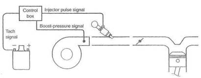
Fig. 7-10. One or two additional injectors for the entire system can provide fuel for low-boost applications but should not he considered for serious power.
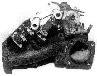
Fig. 7-11. The inline-six Nissan, manifold as equipped with six staged injectors. Original injectors are to the left; secondaries are further outboard, to the right.
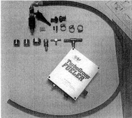
Fig. 7-12. The 'add-on injector' fuel supply will indeed add a useful dose of fuel. The add-on is pulsed with engine speed; duration is controlled by boost pressure.
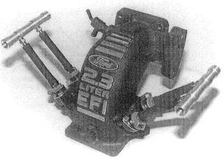
Fig. 7-13. Four staged secondaries can be programmed to operate when under boost.
The injectors must also be sized to deliver the fuel required for the desired airflow rates. Ideally, one extra injector per cylinder is required for serious power. Otherwise, consider this a low-boost-power mechanism.
The preceding paragraphs cover the methods by which EFI may be modified to operate under boost. Prior to selecting a method that suits your requirements, make sure your measurements and calculations are correct. Don't get off on any dopey tangents like turning on cold-start spray nozzles, or any other equally inane schemes, without suitable investigation proving that the scheme meets all the requirements of a properly conceived fuel system.
The EFI fuel injector has a rating of fuel flow per unit time. A huge variety of sizes exist. An equally huge number of units of volume or mass flow are used to rate injector flow capacity. The following will convert cc/min to lb/hr:
![]()
The calculations required to come up with a properly sized injector for a given application are not rigorous. No rocket science here. One simple calculation and the job is done:
![]()
The .55 figure is actually the maximum load brake specific fuel consumption (bsfc) of a typical turbocharged engine. In general, the number of injectors is the same as the number of cylinders. Clearly, one should choose the next larger size than the calculated value, to offer some margin for future improvements.
An injector can be measured for its flow capability by applying a suitable voltage (usually 9, but check the manual) to the injector and 36 psi (stock fuel pres-
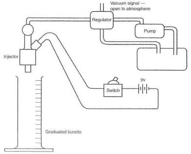
Fig. 7-
sure for most cars and standard pressure for measuring injector flow) to the fuel. Let the fuel run into a graduated burette for one minute. The result is the flow capability measured in cc/min. A couple of 1.5-volt dry cells will hold the injector open just fine.
The fuel requirements of any engine system must be backed up by a fuel supply system. The fuel supply system is the fuel pump, fuel pressure regulator, and fuel lines. The fuel supply system must be able to meet the challenge with a reasonable margin of extra capability. This margin requires a balance between the pump's flow capability and its pressure capability An odd feature of all pumps is the fact that they produce their greatest flow at their least pressure. The maximum pressure rating of a pump is when your thumb is on the outlet of the pump, not letting anything out. In other words, no flow. On the other side of the coin, the maximum flow of the pump occurs when it is free to pump with no restriction (no thumb). The EFI fuel pump is a positive-displacement pump driven by a dc motor. As the work the pump is asked to do increases, the motor slows down. As the motor slows down, the volume of fuel being pumped falls off. To operate EFI systems, we must have fuel pressures of 40+ psi. Therefore we must know, calculate, or measure the fuel flow rates at these pressures.
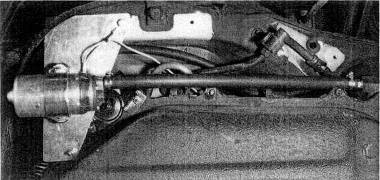
Fig. 7-15. Turbo fuel systems, especially those controlled by a rising-rate regulator, require high-pressure/ high-flow fuel pumps. This Bosch pump will supply 130 psi at flow rates supporting 500 bhp.
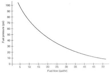
Fig. 7-16. Typical fuel pump flow versus fuel pressure. Fuel pumps deliver less flow with increasing pressure. The engine's requirements must always stay below the curve.
Any given pump will have a flow-versus-pressure curve. These can be hard to come by, but it is not a real challenge to measure a particular pump's capability.
Perhaps the simplest method of determing a pump's capability (particularly if it is already there) is an actual field test, to see if it maintains maximum required fuel pressure to the engine redline. If it does, fine. If not, however, this test provides no data about what is needed.
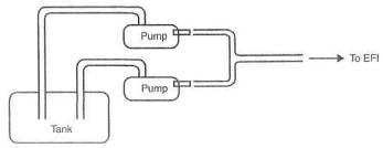
Fig. 7-17. Approximate fuel pump flow requirements versus engine bhp.
The standard method for measuring an EFI pump's flow capacity at a given pressure is to connect it to an EFI pressure regulator and measure the volume exiting the fuel return line. This is the volume of fuel that can be taken from the fuel system at that pressure without the fuel pressure's dropping off. With the fuel pressure regulator's vacuum reference open to the atmosphere, fuel pressure will be 36 psi. This is the pressure used on the chart to determine flow capacity. It is equally easy to simulate fuel flows when operating under boost. Feed a pressure signal to the fuel pressure regulator equal to the boost desired and again measure flow out the regulator return line. This tan be dons with shop air and an adjustable air pressure regulator Fuel pressure will be equal to boost pressure plus 36 psi. Prom calculations of the injector sizes required under maximum load, the total flow required is known. That total is injector capacity times the number of injectors. The number of cc's per minute divided by 1000 is the number of liters per minute. If the point on the chart representing your requirements of flow capacity versus fuel pressure lies beneath the line, all is well. If the point lies above the line, two or more pumps operating in parallel are required.
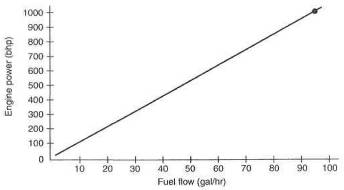
Fig. 7-18. Fuel pumps in parallel should have separate, dedicated fuel pickups.
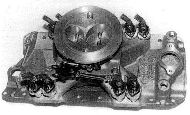
Fig. 7-19. An effective example of converting a four-barrel carbureted manifold to an EFI system. A throttle body replaces the carb; fuel injector bosses are installed at the ends of the ports.
Perhaps not yet recognised for what they really are and for their vast tuning potential, aftermarket. EFI systems will prove the greatest boon for hot rodders since the small-block Chevy. This is the equipment that can make a docile lamb and high-economy cruiser out of a twin-turbo Keith Black 600 cid hemi V-8. Aftermarket EFI indeed offers the opportunity to create the 1000 bhp daily commuter automobile. The singular aspect of EFI that permits this is its fine degree of tuning available over huge intake manifold pressure ranges. By comparison, the finest carburetor in the world has four fuel-flow circuits that can be timed over the range in which it is asked to operate. Over this same range, EFI offers literally hundreds of fuel flow circuitsone for virtually every hundred-rpm band and every inch of manifold pressure. It's equivalent to having 500 main jet circuits in a carb, each one ideally set up for a certain engine load and rpm.
Several aftermarket
companies have introduced EFI systems in the last couple of years. Air Sensors,
in
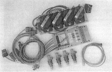
Fig. 7-20. Electromotive, of
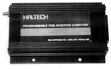
Fig. 7-21. The Australian Haltech EFI has proven durable and versatile for specialty tuners.
More recent
developments, like the Haltech, offer a completely programmable EFI
Electromotive, in Virginia, and Digital Fuel Injection, of
Setting up a functioning EFI system means creating the air throttling mechanism as well as doing the hydraulics. The problems to be solved are exactly the same as the problems discussed earlier in this chapter, plus a few new twists. The hydraulic aspects are the same. Intake manifolding layout must be considered; see Chapter 6. Throttle valving, along with number and positioning of in-jectorsj is also discussed in that chapter.
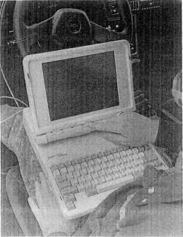
Fig. 7-22. The laptop computer is a basic tool for creating and tuning fuel curves of aftermarket fuel injection systems.
Fig. 7-23. Integration of a flowmeter into the system can be compact. Note the flexible hose to isolate engine vibrations from the flowmeter.
Is there any benefit to draw-through throttle designs on fuel injected cars ?
A noticeable throttle response improvement between gear shifts can be achieved by plating the throttle in front of the turbo when no intercooler is used. Slamming the throttle shut downstream of a pumping turbo simply causes a greater loss of turbo rpm. This lost speed must be reacquired before boost can again be achieved. A downstream throttle with an intercooler will ultimately prove superior if accompanied by a compressor bypass valve system.
Why are changes needed to existing fuel systems?
Carbureted turbocharger systems do not have any requirement for extra fuel delivery systems. The more air drawn through a carb, the greater the pressure drop at the venturi, and thus the more fuel pushed through the main jet. A properly sized and calibrated carb is necessary, and that is all.
Fuel injection systems
are a completely different situation. It is commonly claimed that fuel
injection systems will take care of themselves when a turbo is added. This is
decidedly not true. A fuel injection system is sized for a given engine. A
2-liter unit will not work on a 4-liter engine. The reason for this is that the
airflow meters and fuel injectors are sized for the flow capability of the accompanying
engine, and any substantial increase over stock flow rate will bottom out the
airflow meter. A 2-liter unit airflow meter subject to an infinite airflow rate
might think it's a gorilla
|
Politica de confidentialitate | Termeni si conditii de utilizare |

Vizualizari: 2349
Importanta: ![]()
Termeni si conditii de utilizare | Contact
© SCRIGROUP 2025 . All rights reserved