| CATEGORII DOCUMENTE |
| Bulgara | Ceha slovaca | Croata | Engleza | Estona | Finlandeza | Franceza |
| Germana | Italiana | Letona | Lituaniana | Maghiara | Olandeza | Poloneza |
| Sarba | Slovena | Spaniola | Suedeza | Turca | Ucraineana |
The exhaust manifold plays a key role in all performance aspects of the turbo system. The turbo manifold has many and varied duties to perform. Direct responsibilities include support of the turbo, guidance of exhaust gases to the turbine, keeping exhaust gas pressure pulses moving along intact at a steady pace, and trying hard not to let any heat escape through the manifold walls. To accomplish these chores while glowing cherry red, trying to remain straight, not developing cracks, and hanging in there year after year is not exactly an assignment for boys. An exhaust manifold leads a hard life.
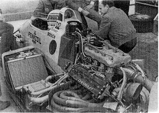
Fig. 10-1. When designing exhaust manifolding, don't hesitate to copy just be sure you're copying the best.
The application, whether competition or high-performance street, will strongly influence material selection, design style, and method of manufacture. Any maximum-effort turbo system will be configured around a tube-style. fabricated manifold, One-off designs, for cost reasons alone, must also be fabricated. A cast manifold is the obvious choice when a large number of parts are to be made.
Heat retention. Clearly, performance of the turbine is in part determined by the temperature of the exhaust gases. It is reasonable, then, to expend some effort toward getting the exhaust gas from the combustion chamber to the turbine with the least possible temperature loss. This is fundamentally true, although the strength of materials at elevated temperatures must sometimes be considered and same form of cooling provided. The thermal conductivity of a material is a measure of that material's ability to conduct heat. Since the objective here is to keep the heat inside the manifold, it is reasonable to try to use a material with the poorest ability to transfer heat.
Stainless steel. Stainless offers an interesting combination of properties. It is low in thermal conductivity, which is certainly desirable. Stainless grade 304 is an excellent choiceeasily welded, crack resistant, and relatively easy to work with. All stainless materials have a very high coefficient of thermal expansion; thus, the design, style, and fit of a stainless manifold must account for this unusual property. For example, a stainless header flange drilled perfectly for an exhaust bolt pattern with .3125-inch-diameter bolt holes attached to a cylinder head with .3125-inch-diameter bolts will shear half the bolts on the first warm-up cycle. Larger-than-normal bolt holes are therefore necessary. Stainless steel enjoys long-term corrosion resistance. Because of this and its low heat transfer capability stainless deserves strong consideration as the material choice for high-performance exhaust manifolds.
Cast iron. Iron alloys offer a designer many options. While not exactly putty in a designer's hands, iron alloys do have the ability to be molded into complex shapes.
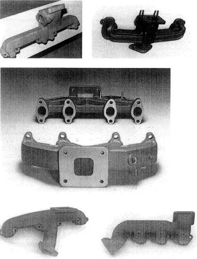
Fig. 10-2. Top left: A manifold design for twin turbos. Note the wastegate per manifold and no provision for a cross tube. Top right: Typical exhaust manifold casting for a V-8. Note the cross-tube connection entering the manifold from directly bellow the turbine inlet. Center: A simple, elegant design for the VW GTI engines. Bottom left; Single V-8 turbo design. The lower flange is the cross-tube connection. from the opposite bank of cylinders. Bottom right: Big-block Chevy single turbo design with a rear inlet for the cross tube
The limits lie with the ability of the pattern makers. The casting process is the only viable way to make an exhaust manifold with a wide variety of section shapes and wall thicknesses. An experienced or thoughtful designer can take advantage of this characteristic to produce a low-surface-area, thin-walled, smooth, constant-section-passageway manifold,
A wide variety of iron alloys exist, but perhaps the most useful for exhaust manifold design is the alloy called 'ductile iron.' Ductile iron's characteristics range from good crack resistance and high-temperature shape stability to free machining, all with a relatively high basic strength.
Cast manifolds remain the territory of the volume producer, due to the expense of creating the necessary patterns and tooling.
Mild steel. Although mild steel has no particular characteristics that make it an ideal choice of exhaust manifold materials, it does, indeed, do almost everything well. This material is inexpensive, easy to machine and weld, and readily available in a wide variety of sizes and shapes. Perhaps its poorest characteristic is corrosion resistance. This can be helped significantly by chrome plating. Ask for industrial-quality plating, which is many times thicker than decorative chrome. Perhaps better than chrome are some of the modern ceramic coatings.
Aluminum. Because of aluminum's poor high-temperature strength and high heat-transfer coefficient, rule it out as a suitable material for an automotive exhaust manifold. In some boating applications where exhaust outlet and manifold surface temperatures must be closely controlled, a cast aluminum manifold with water jackets becomes an ideal choice.
The wall thickness of a particular material will strongly influence the heat transfer, in that the thicker the material, the faster heat will travel through it. This seems contrary to logic at first thought, but consider how fast heat would be drawn out of a high-conductivity, infinitely thick aluminum manifold, as opposed to a very thin piece of stainless surrounded with a nice insulator like air. Heat transfer is directly proportional to surface area. It is therefore reasonable to give considerable thought to keeping the exposed surface area of the exhaust manifold to an absolute minimum. Clearly, the less surface area, the less heat loss. Reducing the amount of ambient air flowing around the exhaust manifold and turbocharger will further reduce heat loss from the system. It is generally not feasible to directly wrap the exhaust manifold with an insulating material, as the manifold material itself will overheat to the point of structural failure.
A further effect on heat transfer out of the exhaust manifold is heat distribution inside the manifold. Hot spots inside the manifold should be avoided, because they can quickly pump a lot of heat out. They are created by sharply angled intersections or by too many exhaust pulses through one segment of the manifold, Keep in mind that the temperature difference between the inside and outside of the manifold is the force that pushes heat through the manifold.
Reversal of the exhaust gas flow back into the combustion chamber during valve overlap is called reversion. Creating an aerodynamic barrier that reduces the reverse flow yet does not impede outward-flowing gases can pay dividends in performance.
In general, much greater freedom exists in the choice of manifold styles when the manifold is fabricated. These choices range from the simple log style, to the equal-length, multiple-tube, individual-runner style.
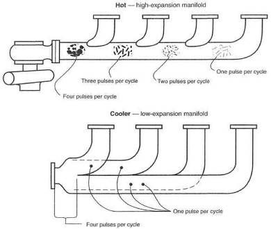
Fig. 10-3. Durability of an exhaust manifold can be influenced by the basic design. A log-style manifold is subject to more heat abuse and thermal expansion than a separate-tube header. Overlapping heat pulses in the log style create extra hot spots and greater expansion.
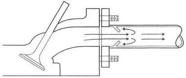
Fig. 10-4. The anti-reversion cone can offer a reduction in exhaust gas reversion, during valve overlap. The cone creates a partial barrier to reversal of flow.
A great amount of research has been done on the performance benefits of various manifold styles. Most of this research, plus the tremendous efforts put into the recent era of turbocharged Grand Prix cars, strongly indicates that the best manifolding is multiple-tube, individual runner style.
Tubing sizes. Almost all applications of a turbo are to an existing engine. Therefore, the choice of tube sizes will usually be dictated by port she and the size of the turbine inlet on the turbocharger. Where a clear-cut choice does not exist, it is best to select the smaller of the sizes available, thus increasing exhaust gas velocity.
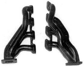
Fig. 10-5. Four-into-one designs for 4- or 8-cylinder engines
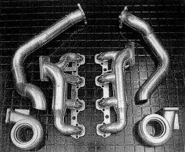
Fig. 10-6. An example of good, compact manifolds. These designs also use weld els.
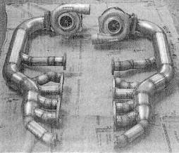
Fig. 10-7. V-12 custom header. The sharp intersections are not ideal for power. Long collector tubes are going to experience large thermal expansion, necessitating flexible braces on the turbos.
The strength of the
manifold will be controlled largely by the wall thickness of the materials. In
a fabricated manifold where wall thickness drops below
A variation of the tube manifold can be constructed based on a cast-steel part called a weld el. Weld els are basically industrial hydraulic equipment, used commonly in oil well and other similar heavy duty applications. These els are available in a variety of sizes and radii, and in either mild steel or stainless. Although heavy and expensive, weld els can be used to form a proper high-strength manifold. Weld els are sized according to pipe nomenclaturethat is, inside diameters.
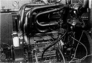
Fig. 10-8. Jim Feulitig's wild twin-turbo Quad 4 featured some of the best headers ever built. Note the particularly smooth collectors.
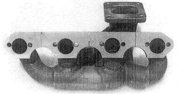
Fig. 10-
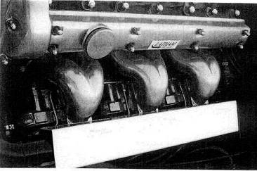
Fig. 10-10. Weld el manifolds as a functional work of art
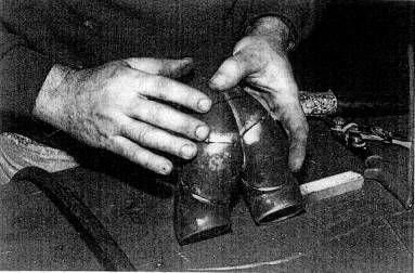
Fig. 10-11. Fitting weld els together to form the triple-turbo Jaguar exhaust manifolds
|
Nominal pipe size |
Bend radius |
Outside diameter |
Inside diameter |
Wall thickness |
Table 10-1. Weld el selection chart for 90 elbows (inches)
|
Nominal pipe size |
Length |
Nominal pipe size |
Length |
|
3/4 x 3/8 |
2 x 3/4 | ||
|
3/4 x 1/2 |
2 x 1 | ||
|
1x 3/8 |
2 x 1 1/4 | ||
|
l x l/2 |
2 x 1 1/2 | ||
|
1 x 3/4 |
2 1/2 x 1 | ||
|
1 l/4 x 1/2 |
2 1/2 x 1 1/4 | ||
|
1 1/4 x 3/4 |
2 1/2x 1 1/2 | ||
|
1 1/4 x 1 |
2 1/2 x 2 | ||
|
1 1/2 x 1/2 |
3x1 | ||
|
1 1/2 x 3/4 |
3 x 1 1/4 | ||
|
1 1/2 x 1 |
3x 1 1/2 | ||
|
1 1/2 x 1 1/4 |
|
3 x 2 | |
|
3 x 2 1/2 |
Table 10-2. Weld el selection chart for concentric and eccentric reducers (inches)
The casting process lends itself to simpler designs, due largely to the complications and costs of patterns. These designs usually adopt log-style manifolds-good for production but not quite so good for maximum performance. It is necessary to understand that a cast manifold can deliver very good performance, but it is not race car hardware.
Early in the planning of the exhaust manifold design, consideration must be given to location of, and bleed-off to, the wastegate. The principles involved in integrating the wastegate into the system are that bleed-off to the wastegate must occur after all exhaust pulses headed for the turbo have been combined into one tube, and the flow path must be streamlined.
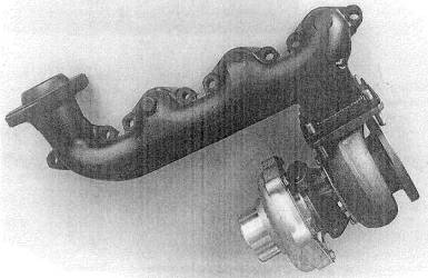
Fig. 10-
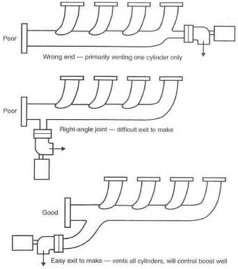
Fig. 10-13. Integration of the wastegate into the exhaust manifold
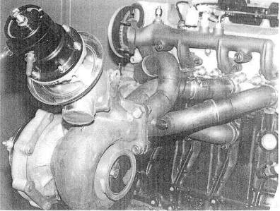
Fig. 10-14. The
Changes in the shape of a manifold as its temperature rises from ambient to operating must be considered during layout. Heat-induced warpage can cause se-vere problems with constant exhaust gas leaks. Warpage is caused by unequal temperature distribution through the material of the manifold. As an example, the header flange will not reach the same temperature as a segment of the tubing or the collectors; therefore, it will not change length as much. These varying changes in length will induce warpage if they are not accounted for in the design. Each port flange, for example, should be separate from the others.
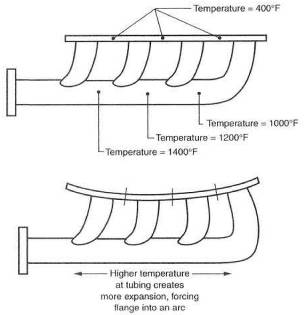
Fig. 10-15. Tempera-ture-induced warpage: the header is forced to warp due to uneven temperature distribution between the tubes and the flange. The fix is to sever the flange into as many segments as there are ports.
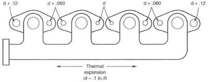
Fig. 10-16. Thermal expansion can fracture header bolts. This can be avoided by making the bolt holes progressively larger as their distance from the center of the manifold increases.
Thermal expansion characteristics will require attention to bolt hole sizes, particularly at the cylinder head. Tight, close-tolerance bolt patterns can actually cause fastener failure by placing the fasteners under severe binding when a manifold reaches maximum operating temperature. The solution to this problem is enlarging the holt hole size as it gets farther away from the center of the manifold. This is essential when stainless steel is the material used. On long engines, like six-cylinder inline, the designer should consider using two manifolds, with interconnections from a tubular flex joint. This type of slip joint is common on aircraft and large industrial engines.
Selection of fasteners is a twofold decision. The heat involved in a particular joint determines the choice of material, while the type of joint determines whether a bolt or stud is used.
The idea of holding
parts together at the operating temperatures induced by a flat-out turbocharger
system is cause for some thought. Almost any mild steel will have its heat
treat cooked out of it. Mild steel will eventually oxidize to the point where
fasteners are corroded virtually to the base materials, Cadmium plating will
burn away at these temperatures. The most reasonable solution to fastener
problems is stainless steel. Stainless steel bolts work better at temperatures
above
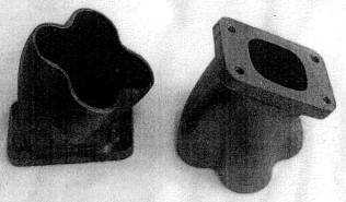
Fig. 10-17. Cast iron collectors suitable for 4-and 8-cylinder headers
Depending on the style of joint, three fasteners are possible: through-bolt, stud, or bolt. Observe the following guidelines:
A through-bolt with a nut (a con-rod bolt, for example) is always the first choice,
A stud anchored in a threaded receiver (cylinder head to exhaust manifold, for example) is a decent second choice,
Last and clearly least is a bolt screwed into a threaded receiver. These joints cannot stay tight unless secured with safety wire. Use on]y as a last resort.
Large, heavy, flat washers are necessary, as are lockwashers. Forget using any form of spring lockwasher; as the heat treat merely gets cooked out. Interference-style lockwashers, with ramps, ridges, or serrations, are the only lockwashers that are survivors.
Stainless mechanical locknuts are able to keep a positive lock at high temperature. Copper-alloy locknuts cannot cut the temperature; they simply sag.
Although the function of a gasket seems obvious, the gasket can also be used as somewhat of a thermal barrier. Some joints need gaskets for sealing, while others benefit solely from the reduction of heat transfer. The mating surfaces of two parts operating at about the same temperature don't necessarily need a gasket. The turbo attachment to the manifold is such a joint. A wastegate attachment is quite the opposite, however It is desirable to reduce heat in the vicinity of the wastegate diaphragm, to improve the diaphragm's life expectancy. A gasket here serves as a useful heat block. This same condition exists at the tailpipe joint to the turbo and the wastegate vent tube to the wastegate.
Gaskets obviously take
a serious beating in any exhaust system. The presence of the turbo doesn't
help the situation. In certain situations where the quality of the machining
permits, the best solution to a gasket problem is to leave the gasket out. This
is particularly viable between two cast iron surfaces.
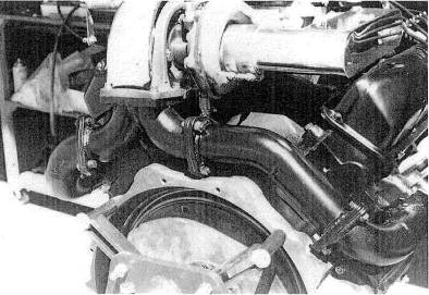
Fig. 10-18. Excellent exhaust plumbing details on a single-turbo V-8
When a gasket is
obviously required, the metal/fiber/metal laminated type is perhaps the best
all-around combination of sealing gasket and insulator for the high-heat
environment of the turbo. A simple stain less-steel-sheet gasket or annealed
copper gasket is also an excellent choice. The latter two are usually .02-
Eliminating gaskets is a valid design objective. With thick flanges and careful surface machining, by and large, most gaskets can be eliminated. There is an element of logic to the idea that an absent gasket can't blow.
What constitutes a proper exhaust manifold?
An exhaust manifold is a complicated design exercise involving many parameters. The single most important parameter is the material, and cast iron is the best material for typical street applications. Plain steel is the poorest choice, because it oxidizes rapidly at high temperatures, flakes off, and ultimately cracks. Internal streamlining is important, to avoid pumping losses. Another critical design feature is flow velocity. Exhaust gas must not be forced to speed up and slow down, since it will lose considerable energy otherwise available to the turbine. Smooth, constant-velocity flow is ideal. Heat retention is important. The more heat that can be retained inside the manifold, the less the thermal-lag portion of the total turbo lag. A design that allows exhaust gas pulses to arrive at the turbine at regularly spaced intervals is ideal but difficult to achieve.
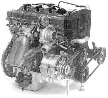
Fig. 10-19. Note the 'doubling back' of the exhaust manifold on this 1986 YBB engine fitted with a turbo. This placement has permitted an unusually compact layout while maintaining a smooth 4-into-l design.
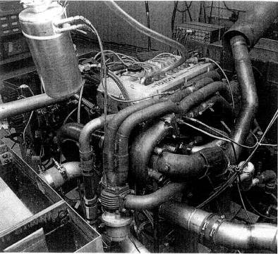
Fig. 10-20. One of the early
Do the joints interfacing the turbo have any reliability problems ?
Gaskets between exhaust manifolds and turbos are often unreliable due to the extreme heat. The most practical solution to this problem is precision fiat surfaces that seal without gaskets.
|
Politica de confidentialitate | Termeni si conditii de utilizare |

Vizualizari: 4130
Importanta: ![]()
Termeni si conditii de utilizare | Contact
© SCRIGROUP 2025 . All rights reserved