| CATEGORII DOCUMENTE |
| Bulgara | Ceha slovaca | Croata | Engleza | Estona | Finlandeza | Franceza |
| Germana | Italiana | Letona | Lituaniana | Maghiara | Olandeza | Poloneza |
| Sarba | Slovena | Spaniola | Suedeza | Turca | Ucraineana |
STRUCTURAL MECHANICS
MODULE
LABORATORY REPORT
Introduction
Aim & Objective
The main objective is to measure Youngs modulus for the steel and wooden beam using symmetrical loading arrangement. Measurement of the radius of curvature between the supports allows Youngs modulus to be determined. The aim is to obtain values from a single point method, and a graphical gradient method which are to be compared.
Theory
The bending moment, M, about the centre point (taking clockwise as +ve) is:
![]()
M = Fa where F= mg
When applying the force with weights of mass m, the force is of course F=mg, where g is acceleration due to gravity = 9.81 m/s². Therefore it is easy to show that the bending moment is constant at any point between the supports.
The general beam bending equation which relates radius of curvature to bending moment is
![]()
Where E is the Youngs modulus, M is the bending moment, R is the radius of curvature and I is the second moment if area.
The second moment of area of a beam of width b, and depth d is given by where d is measure in the direction of bending. The second moment of area is:
![]()
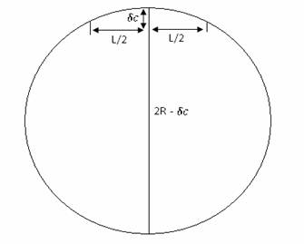
The deflection at the centre of the bam can determine the radius of curvature.
Intersecting Chords Theorem:
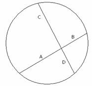 A circle that has two intersecting chords, and
lengths a,b,c and d as shown, we have a x b = c x d
A circle that has two intersecting chords, and
lengths a,b,c and d as shown, we have a x b = c x d
Using measurements of displacement at the centre, ![]() we have:
we have:
![]()
Assuming that ![]() we can neglect
we can neglect![]() , giving:
, giving:
![]()
If we substitute equations 1, 3 and 4 into equation 2 we get:
![]()
And therefore E can be calculated from the gradient method:
Steel beam
Width b Depth d
|
0.025 [m] |
|
|
0.024 [m] |
|
|
0.025 [m] |
|
|
0.026 [m] |
|
|
0.025 [m] |
|
|
0.025 [m] |
|
|
Average: 0.025 [m] |
|
|
0.005 [m] |
|
|
0.004 [m] |
|
|
0.006 [m] |
|
|
0.005 [m] |
|
|
0.005 [m] |
|
|
0.005 [m] |
|
|
Average: 0.005 [m] |
|
L = 0.5 [m] a = 0.338 [m]
Putting weights
|
Mass on each hanger |
Deflection |
|
0.1 [kg] |
20 x10-5 [m] |
|
0.2 [kg] |
41 x10-5 [m] |
|
0.3 [kg] |
62 x10-5 [m] |
|
0.4 [kg] |
80 x10-5 [m] |
|
0.5 [kg] |
100 x10-5 [m] |
Removing weights
|
Mass on each hanger |
Deflection |
|
0.5 [kg] |
102 x10-5 [m] |
|
0.4 [kg] |
79 x10-5 [m] |
|
0.3 [kg] |
61 x10-5 [m] |
|
0.2 [kg] |
42 x10-5 [m] |
|
0.1 [kg] |
19 x10-5 [m] |
Average of the loading and unloading displacements
c = 101 x10-5 [m]
Single point calculations
Highest applied force
Find radius of curvature
R =![]()
R ![]() m
m
Bending Moment
M =
M = 0.5x9.81x N-m
Young Modulus
E = ![]()
![]()
![]() E =
E = ![]()
E = ![]() = 204 GPa
= 204 GPa
Lowest applied force
Radius of curvature
R =![]()
R ![]() m
m
Bending Moment
M = ![]()
M = 0.1x9.81x N-m
Young Modulus
E = ![]()
E ![]() = 206 GPa
= 206 GPa
Gradient method
Plot the graph force against deflection
|
Deflection |
Force |
G |
Mass |
|
[m] |
[N] |
[m/s2] |
[kg] |
|
[m] |
[N] |
[kg] |
|
|
[m] |
[N] |
[kg] |
|
|
[m] |
[N] |
[kg] |
|
|
[m] |
[N] |
[kg] |
Find Bending Moment
M= (3/2) ((a*L^2)/ (b*d^3))
Where,
a=0.3375
L=0.5
b=
d=0.0052
M= N-m
Find Gradient
G= (change in y-coordinate)/(change in x-coordinate)
G1= G2= Gaverage=
Find Young Modulus
E=G*M/109 GPa
Wooden beam
Width b Depth d
|
0.026 [m] |
|
|
0.025 [m] |
|
|
0.025 [m] |
|
|
0.024 [m] |
|
|
0.026 [m] |
|
|
0.025 [m] |
|
|
Average: 0.0252 [m] |
|
|
0.006 [m] |
|
|
0.005 [m] |
|
|
0.005 [m] |
|
|
0.005 [m] |
|
|
0.005 [m] |
|
|
0.004 [m] |
|
|
Average: 0.005 [m] |
|
L = 0.5 [m] a = 0.338 [m]
Putting weights
|
Mass on each hanger |
Deflection |
|
0.1 [kg] |
174 x10-5 [m] |
|
0.2 [kg] |
360 x10-5 [m] |
|
0.3 [kg] |
539 x10-5 [m] |
|
0.4 [kg] |
719 x10-5 [m] |
|
0.5 [kg] |
898 x10-5 [m] |
Removing weights
|
Mass on each hanger |
Deflection |
|
0.5 [kg] |
898 x10-5 [m] |
|
0.4 [kg] |
718 x10-5 [m] |
|
0.3 [kg] |
537 x10-5 [m] |
|
0.2 [kg] |
359 x10-5 [m] |
|
0.1 [kg] |
172 x10-5 [m] |
Average of the loading and unloading displacements
c = 101 x10-5 [m]
Single point calculations
Highest applied force
Find radius of curvature
R =![]()
R ![]() m
m
Bending Moment
M =
M = 0.5x9.81x0.338 = 1.658 N-m
Young Modulus
E = ![]()
![]()
![]() E =
E = ![]()
E = ![]() = GPa
= GPa
Lowest applied force
Radius of curvature
R =![]()
R ![]() m
m
Bending Moment
M = ![]()
M = 0.1x9.81x N-m
Young Modulus
E = ![]()
E ![]() = GPa
= GPa
Gradient Method
Plot the graph force against deflection
|
Deflection |
Force |
G |
Mass |
Find Bending Moment
M= (3/2) ((a*L^2)/ (b*d^3))
a=0.3375
L=0.5
b=0.0252
d=0.0055
M=30186755.39 N-m
Find Gradient
G= (change in y-coordinate)/(change in x-coordinate)
G1=545.758 G2=545 Gaverage=545.379
Find Young Modulus
E=G*M/109=16.79 GPa
Results
|
Steel beam Young's modulus (E) in GPa |
Wooden beam Young's modulus (E) in GPa |
|
|
Table quantities | ||
|
Gradient Method | ||
|
Single point calculations HAF | ||
|
Single point calculations LAF |
Conclusion
After finishing a laboratory session calculations, it was compared with table quantities and analyzed which method is most precise and accurate.
Looking at the graph was observed that gradient method is more precise for wooden beam, then single point method, but if we look at steel beam result it is obvious that single point method is more correct then the first one.
However especially for me gradient method was easier, because it didnt need to much calculations and formulas. As single point method is more complicated I did twice calculations with incorrect answers, thats why I would prefer gradient method instead single point method.
|
Politica de confidentialitate | Termeni si conditii de utilizare |

Vizualizari: 1823
Importanta: ![]()
Termeni si conditii de utilizare | Contact
© SCRIGROUP 2025 . All rights reserved