| CATEGORII DOCUMENTE |
| Bulgara | Ceha slovaca | Croata | Engleza | Estona | Finlandeza | Franceza |
| Germana | Italiana | Letona | Lituaniana | Maghiara | Olandeza | Poloneza |
| Sarba | Slovena | Spaniola | Suedeza | Turca | Ucraineana |
DOCUMENTE SIMILARE |
|
TERMENI importanti pentru acest document |
|
Designing your own power supply
with some practical examples
Ever since I wrote my first texts on power supplies, I have been answering queries about them. It's not that I'm tired of it, it's just that a general approach is much more practical.
Another problem is that people always ask me 'What's that component, ?' So, to avoid that, I have provided lists of materials used AND hi resolution schematics, downloadable at will.
Rather then theorize, let's get down to it with some practical examples.
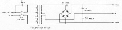
What we see here is the most usual type of power amp power supply. SW1 is a simple on/off switch, it is bypassed by C1, and connects the power transformer T1 to the mains. T1 has a dual secondary, the outputs of which are fed to D1, which is a full wave bridge rectifier. Its job is to rectify AC into DC voltage. However, since bridge rectifiers also act as FM detectors, what comes out of it is then filtered by C2 and C3, in this case two 10,000uF capacitors.
So what's wrong with this? Functionally, nothing - it will work, make no mistake. It does work in say 60% of all audio devices made today. You might say it's a time proven design.
It works, yes - but good it is not. The chief problem of this setup is that it assumes two large capacitors are sufficient to clean everything up, to act as energy reservoirs for the entire unit and to have no inherent adverse effects. None of which is so, of course.
First, it is well known, and can be proved very easily, that large capacitors will filter well lower frequencies, such as 50/60 Hz, but will filter high frequencies rather poorly. This means you are likely to encounter RF problems, either directly (as, for example, a sound reminding one of bird chirping), or indirectly, as an elevated level of intermodulation. Next, large capacitors do filter better than smaller ones, but are also slower than smaller ones (all other things being equal), so the subjective speed of your amplifier in particular greatly depends on the quality of those capacitors - which means you lose, because this sort of setup is typical of the economy class, which is HIGHLY unlikely to use extra quality capacitors.
The rising output impedance of the large capacitors will also reflect in your damping factor - by how much is anybody's guess, because the capacitor is only one factor of several which determine your damping factor. But this, in conjunction with the capacitor's natural rising inductance component, could also cause uncertainties in operation, and even instability by oscillation.
I could go on and on, but you get the point - this is quick, dirty and cheap, which is why it's done so much.
Tweaking
If you own a unit with this type of power supply, the most obvious tweaking choice would be to exchange the filter capacitors supplied with better quality units from a reputable source. Likely candidates are Nichicon, Elna, Siemens/EPCOS, Fischer&Tausche, Roederestein, etc.
Before unsoldering anything, measure capacitor size (height and width) and its pinouts; you don't want to be stranded with excellent quality caps you cannot install because of different pin sizes and/or distribution, or too great physical size. The values you can read off the capacitor; for example, if it says '6,800uF/50V', this means the capacitance is 6,800 microfarads and operating voltage is 50V. It's always best to use the same size and voltage if possible, just better quality, which often means larger physical size (since quality implies both better foil and more of it inside).
Also, carefully note plus and minus - this is MOST important! Remember that a large electrolytic capacitor turned the other way around will act like a shrapnel grenade! Check and double-check before switching on the power.
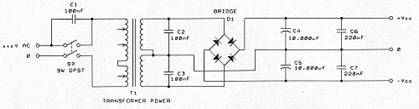
Obviously, the above is a modified version of the first schematic. It adds two 100nF caps before the rectifier and two 100nF caps after the large capacitors. Their job is to filter out the high frequency rubbish entering through the mains, but also the airborne junk picked up by the rectifier. A side effect is that they partially act as compensation of the large capacitors' inductance, but while this is so, don't count on too much effect there. However, they do reduce the possibility of instability or oscillation resulting from power supply related problems.
Better commercial units use something along these lines. The added cost is not too much of a problem, at least not so on an individual basis. Typical candidates for this job are Wima, Siemens, etc polypropylene capacitors. I would suggest going for high voltage ratings, 250 VAC being the minimum, 400 VAC being the recommended value.
Tweaking
This one is easy to tweak. You can simply select a small value capacitor, make sure there's space enough to add and solder it directly across the large capacitor pins. My suggestion is to use a 220 nF/400 VDC capacitor, such as those made by Wima, Siemens, etc. Make sure it's a polypropylene unit, and it will very likely be not so small. You may have to bend it during installation, so don't hurry in cutting its pins straight off.
The differences will most likely be subtle rather than in-yer-eye. Listen for changes in the high range, that's where they will be most obvious, such as decreased harshness, clearer sound with better definition and perhaps minor subjective improvements in speed (but if this happens, you'll know your caps are in bad need of a change, and fast, they're either dried up, or are of very poor quality).
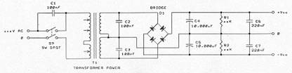
The third version was much used by ReVox in its days of fame. It's based on the second schematic, but adds a pair of resistors across (in parallel with) the large capacitors. These resistors are called bleeders, and their job is to discharge the capacitors when the unit is switched off.
So far, we haven't even mentioned this problem, and in fact, very few people do. It's a fact that the energy stored in the capacitors has to go somewhere when the unit is switched off. Usually, they are left to discharge on their own. This is not good for them, because it takes a very long time and is never really complete, which means the capacitors have to suffer a sort of half-life, neither charged, nor discharged, for considerable periods of time. Discharging them properly, within a reasonable period of time and fully, will enable them to last longer and operate better. In terms of the sound we hear, assuming the initial capacitor selection was well made, we will be hearing better and more dynamic sound for a longer period of time, although this will not prevent capacitor aging, this will only prolong it.
Tweaking
Because of their never insignificant size, bleeders are never easy to install as a later option. For them to do any reasonable work, you will need at least 2W resistors, and 5 or 10 watts is even better. The greater the power rating, the faster they can discharge the capacitors, but on the other hand, something is better than nothing.
You can work out the values yourself, remembering that current equals voltage divided by resistance, and power equals this current times the supply rail voltage. Make sure the power rating of the resistor is at least four times what you will need, because it will tend to heat up quite considerably in the period it takes to discharge the capacitors. I would prefer to see twice that; so, if you have a 2W resistor, work out its value so that current times voltage comes out as no more than 0.4-0.5 watts.
As for the discharge time, obviously the more power the resistor can soak up, the less time it will take the capacitor to discharge. But don't let this induce you to use large power resistors for the fun of it, try to strike a reasonable balance between discharge time and your desires to make it instantaneous. As an example, let's say you have a +/- 40V supply with 10,000uF/63V electrolytics of the snap-in type. If you were to use a say 6K8/2W carbon resistor, the current would be (40:6,800) 0.0059 A, or 5.9 mA. A typical snap-in capacitor of that type will provide around 4.6 amperes of current on demand, but this is when it is fully supplied with nominal voltage. Not to dig too deep into the many details one would have to dig up, do use that 6K8/2W resistor, it's quite enough.
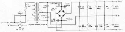
Above we see a developed, or elaborated on version, of the previous examples. It differs in two respects. The first is that the rectifier diodes are now bypassed with small value capacitors (22 nF). This is always desirable because it reduces diode switching noise by a very considerable amount, resulting in cleaner DC leaving the bridge and with most surges removed.
The other difference is that the filter capacitors have been put in parallel. This has two major effects, the first being that you double the available capacitance, and hence double the energy storage available to the power stages. Typically, this shows up in improved bass, since bass is the main energy requirement customer, but also in a general feeling of more relaxed sound. Quite expected, given the much improved energy storage, enabling the power stage to dealer with any and all transients much more easily.
The second major effect is that the output impedance of a single capacitor has been halved, assuming you use exactly the same second unit. This means easier current delivery and improved amplifier damping factor, perhaps not by much, but a little is for sure. Any amplifier's damping factor, or its output impedance, is determined at least in part by the power supply output impedance (though there are other factors as well), so while the improvement may not be capital, it will be there, and every little bit helps.
Tweaking
I have never see a case where a second pair of usually large capacitors could be added to an existing pair. The problems of space are usually unsolvable, and to add more, you often have to resort to adding a whole new case with usually a larger power transformer and filter banks - but this is no longer tweaking, this is rebuilding, a whole new ball game.
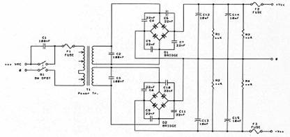
And so we come to just about the best there is short of full voltage regulation. Essentially, this is the same as the previous example, but the number of bridge rectifiers has been doubled. The zero line is then taken from opposing bridge rectifier polarity (the minus side on the plus bridge and the plus side on the minus bridge). This has several benefits: 1) it effectively isolates the transformer from the audio electronics and is bettered only by full voltage regulation, 2) it makes the plus and minus sides independent of each other, which theoretically allows for better reproduction of asymmetrical signals, 3) it reduces power supply output impedance, and 4) it doubles the current capability of the power supply, allowing for better transient reproduction and faster charging of specified and bigger electrolytic capacitors. In effect, it makes the power supply stiffer.
The downside is obvious - the cost and the added complexity. However, this is the way many high end power amplifiers are made, and even some in the upper echelons of the middle class (e.g. Harman/Kardon's now discontinued HK 680 integrated amplifier).
Personally, this is the only way I ever do it. You are not forced to use heavy duty bridge rectifiers, and in fact, this concept goes a long way towards making the actual outlay of power supplies simpler to make. Consider - if you want powerful rectifiers, but are pressed for space, instead of being forced to use bulky powerful units, you can now use simpler to install BxxCyyyy series in standard plastic package, with in-line pins. This has the added benefit of reducing wiring and being far more compact, which you always want.
Tweaking
If you have this, then there is nothing special to tweak, except to exchange existing components for better quality ones, possibly adding larger capacitors. This is as good as it gets, unless you want to go for full voltage regulation.
And on the electronics side
So far, we've looked at the power supply proper. Let's take a look at what's on the electronics side, because while this may not be located near the power supply, it is in fact connected with it because it's in the way the power flows towards the output stage.
One of the problems always encountered to a greater or lesser degree is picking up of airborne and mains induced RF interference. If this is allowed to get to the power supplies and be passed on to the audio electronics, it will surely cause trouble. How much and in what way remains to be seen, but trouble there will be, if in no other manner, than at least in a loss of clarity. But it can be much worse, all the way to making your power output stage unstable and even inducing it to oscillate.
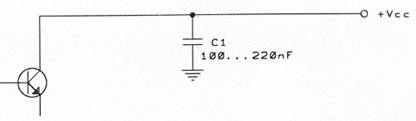
The above is the simplest and most common arrangement. All that stands between the power stage and the power supply input is one capacitor, typically 100220 nF. Attempts will be made to put it as near the power stage as possible, which is good.
This will work, as it indeed has worked for the last 30 odd years. How well depends on the quality of the capacitor much more than on its actual capacitance, meaning that a high quality, high voltage polypropylene cap of 100 nF is much better to have than a low quality, low voltage 220 nF cap.
High end manufacturers will make much play of this capacitor, stressing its quality, voltage, etc. My experience is that this is just marketing (not to say hype) once you have gone over a certain point, the obvious question being where is that certain point. In my experience, once you have put in a Wima or Siemens polypropylene capacitor, rated at 400 V DC or better, you have nothing left to gain by using fancy caps costing an arm and a leg. Except of course a nice bill to foot.
While this will work, I feel this is an oversimplified approach which leaves far too much to be desired. It's quick and easy, and in my view, that's it's only virtue.
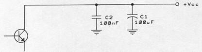
The above is an elaboration of the first example. It uses a classic electrolytic capacitor first, with the objective of filtering out the worst of the junk at lower frequencies, where its internal impedance is still low, and is bypassed by the same small value capacitor as in the first case. The theory is that between the two of them, they will filter out most of the junk still left in the power supply rails.
It can be shown quite easily on any half decent oscilloscope that this is in fact so, and that the resulting power will be cleaner than with the small value cap only. In audible terms, you may obtain somewhat cleaner and less harsh high frequency (10+ kHz) sound, assuming the electronics are good.
Just how effective this may, and how large or small the second cap should be will depend on the quality of the 100uF capacitor. I would recommend you save no money here, and in fact, I would strongly suggest you be lavish here. Buy the best you can, and don't skimp on voltage, forget everything below 100V, keeping C2 an equally high quality device, still rated at 400 VDC or better. Likely candidates for C1 are products from companies such as Nichicon, Elna, Siemens/EPCOS, Roe (Vishay/Roederstein), Fischer&Tausche, etc.
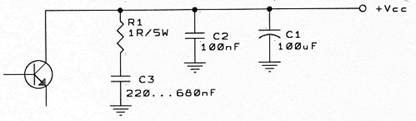
Lastly, we see above the most elaborate arrangement of the lot. As before, we have the larger and the smaller capacitors, but we now add a resistor with a capacitor to the ground. This RC network has an interesting job to do - it should compensate for the large power capacitor stray inductance.
Residual capacitor inductance can lead to many unwanted side-effects, from less than possible quality of high frequency sound, via reduced response speed to fast transients, even down to stability problems, though this may become a problem when using very poor quality capacitors indeed. However, high frequency harshness, often associated with solid state, can either be much reduced, or all but eliminated by using this circuit.
On the other hand, this is a deceptively simple circuit. Just looking at it, one is tempted to say - hey, this is simple, no big deal, just dump them in and go. Not so, I'm afraid.
Consider its primary function - to compensate. Compensating implies you know what and where to compensate, which the vast majority of tweakers do not know and cannot know unless they own some expensive and bulky lab equipment. But they have ears, and can work this on hearing alone, although this means much experimenting, much soldering and unsoldering (as if that's a problem with straight tweakers).
Next, to compensate well, you cannot use just any old component you run across, you need high quality components. Before you sigh, let me add this - they do NOT cost astronomical amounts of money. In Europe, total cost is below 10 euros per channel, or below 20 euros for a dual mono configuration, and while not easy, it can be retrofitted to many amplifiers.
But in principle, this has been used for many decades now; as an example, Professor Matti Otala's legendary TIM amplifier (later built and marketed by Electrocompaniet of Scotland and Norway), as published in IEEE in 1972, used this method with excellent results.
Personally, I wouldn't dream making a power amp without this.
Tweaking
The RC network shown above can be added subsequently to many, though not all, commercially available units. Check first to see if it's not already there, but chances are it's not.
The overall effect assumes a certain set of parameters which must be achieved. Since it's highly unlikely you can measure the proper data, you are left to your own devices. Fortunately, these include your ears, which is basically all you REALLY need.
Both values shown are arbitrary; therefore, you need to pick one and determine it, and then adjust the other for best overall effect. I would advise you use Motorola's MPC series of high power metal film resistors; they are affordable, very compact for their power ratings of 5 (series MPC71) and 10 (series MPC72) watts. Use 1.1 ohms, and while in most cases the 5W version would be sufficient, I still advise you to use the 10W version. Or two lower powered version 2.2 ohm resistors in parallel, if you must.
Buy polypropylene capacitors with values of 680, 470, 330 and 270 nanofarads; 99% probability one of those values will be the best. It will depend on the quality of your capacitors, their number and configuration. Start with the smallest value, i.e. 270 nF, and work your way up. Solder it in as near to the power devices as you can and sit back and listen. Remember it will be a few days for the components to burn in, so do be patient. Change and repeat as many times as you must, and in the end you will get it just right for you.
Designing
All that is very nice, but what if you are just designing your own power amp power supply? How would you go about it then?
Well, I suggest you use the above schematic with twin bridge rectifiers; that is a time proven design which never fails.
What you need is energy, and energy is a product of voltage and capacitance in this case. There is a very simple formula which is not terribly precise, but is quite true nevertheless and is very helpful in designing:
Available energy (joules) = 1/2C x Vsquared,
Where 1/2C applies to the total capacitance in Farads on one side of a power supply, and Vsquared is the voltage of that one side of the power supply. '1/2C' means that what you have hanging on the plus side will also be present on the minus side of the rails.
An example: say your supply voltage is +/- 40V, and say you have two capacitors each rated at 10,000uF in your amp. Your total available energy reserve would then be:
0,01 (40x40) = 16 joules, or 8 joules per channel.
But say, how much energy do you need in the first place?
A rough and ready answer would be 1 joule per every 10W of dissipated power. A more cautious, and in my view a more realistic answer would be between 1 and 2 joules per every 10W of dissipated power, depending on how awkward or difficult your load impedance is. As we all know, speakers are everything but straight resistors, so it's wise to think in worst case terms. Nobody got hurt by having spare energy reserves available, but many were let down by poor energy reserves.
Back to the above example. Assuming you use separate, higher voltage power supplies for the voltage gain stages (and if you don't, you should!), we can assume that the driver and power transistor will each exhibit a 0.65V drop across them. Therefore, our best case voltage available to the signal will be:
40 - 1.3 = 38.7 V peak, which is
38.7 : 1.41 = 27.4V RMS.
Thus, the maximum power is:
Vrms squared : load impedance = watts, or
(27.4x27.4) : 8 = 93.8W/8 ohms.
In real life, this will be less, probably around 80-84 W/8 ohms, for many reasons, one of which is that most power supplies sag (drop) when stressed. The more powerful your transformer, the less sag you will have. However, if your entire amplifier is ran off this voltage, your overall voltage drop across more transistors will decrease the maximum available output power further, so 80-84W is realistic.
Realistic into 8 ohms, because to keep up the ideal voltage across a 4 ohms load, you would need twice the power in watts, and into 2 ohms twice again. While this will mean high load tolerance and small power decreases when the amp is pushed into difficult but very real world speakers, this also means tremendous increases in the power supply.
Consider just this - let's say you're happy with 80W/8 ohms. This ideally becomes 160W/4 ohms and a whopping 320W/2 ohms. In terms of current alone, this is:
Sq. rt [(2x80) :8] = 4.47 amperes
Sq. rt [(2x160) : 4] = 8.94 amperes
Sq. rt [(2x320) : 2] = 17.89 amperes.
The next decision you need to make is whether you want the above as continuous capabilities, or are you going to be reasonable about it. If you're going to be reasonable about it, settle for continuous power into 4 ohms and let impulse power into 2 ohms be what it can - and it won't be small, if you've done everything right.
Settle for a transformer at least 10% above your maximum continuous power requirements; in the above case, 160+10% means a 176 VA transformer. Since this is not a standard or usual value, go for a 200 VA transformer per channel, or a 400 VA transformer for both channels.
160W/4 ohms requires 1632 joules of energy. If you want good load tolerance and high low impedance power outputs, assume 32 joules. To obtain this, assuming your supply rails are still +/-40V, you will need 20,000uF of capacitance, or two 10,000uF capacitors in parallel, per every supply rail, or 40,000uF per channel, or 80,000uF for a stereo amplifier. Check it out:
(40x40) 0.02 = 1600 x 0.02 = 32.
Now, let's assume you start being greedy, and decide to make a killer 100W per channel amp. And I mean a killer, at least from the power supply capability side. You want separate, fully regulated supplies for the voltage gain stages, so the big power supply is for the current gain stages only - but in return, you want the amp to really kick ass.
Looking at the virtual schematic, we note only the driver and power stages will be fed off this power supply, because the predriver is fed from the stabilized power supplies, so as to provide extremely stable initial current gain. Fine. So we have 100W/8 ohms, and all we have to decide now is how much dynamic headroom we want. Dynamic headroom is simply the difference between the nominal power level and the clipping threshold of the amplifier, or the point of no return. Since we are into fabulous power supplies, we don't need too much of a headroom, say 30-40 watts over the nominal 100W.
So, let's determine the required power supply rails first, assuming we are happy with 140W of clipping threshold:
Sq. rt [(140x2) 8] = 47.33 V.
Add the 1.3V drop across the driver and output stage, and you have 48.7V, round it off at 49.35V. Why so, you ask? Because when you divide this by the square root of 2, or 1.41, which happens in the bridge rectifiers, your transformer secondary voltage is (49.35 : 1.41) 35V even. Just make sure this voltage is deliverable at full load on; you see, transformer manufacturers almost never specify the conditions under which a secondary voltage will be delivered, but they sometimes specify their 'regulation'. This 'regulation' is the difference in output voltage with zero load and maximum load on, and can be anything from 10% to 2%.
Working backwards, if the transformer you bought delivers 35V with the load off and has a regulation of say 5%, when stressed it will deliver 1.75V less than 35V, or 33.25V, which will become 46.88V after the rectifiers. Obviously, this will decrease our impulse power output to 138W/8 ohms. This may or may not be significant to you, that's up to you. I always specify my transformers with full load on voltages.
Now, we want our amp to be able to deliver 100W into 8 ohms continuous. This implies 200W into 4 ohms and 400W into 2 ohms also continuous. This time round, let's design for full continuous power output into 2 ohms, and hope your power devices and heat sinks can take the punishment.
400W/2 ohms means a minimum per channel power transformer of 500 VA (600VA would be better). Being pessimistic, we will assume worst case speakers and say 2 joules per every 10W of dissipated power, meaning we need 80 joules of energy storage per channel. A tall order.
We have +/-49V supplies, and if we use three 10,000uF caps in parallel per supply rail, we will have energy storage of 72 joules, which is close enough. But to have this, we need a total of 12 10,000uF capacitors in the amp, which even using cheap units, becomes expensive and bulky. And when you come to high quality capacitors which are far from being cheap, you start realizing why high quality power amps cannot be cheap.
A trade-off
To offset such costs, the industry at large (but thank God, not all of it) uses various tricks, the most favorite one being to use uncommonly high supply rails. A typical mass produced amp delivering 100W/8 ohms will use supply rails of 5560V. They will also use cheap power transformers, which will drop this by 710% easy when pushed hard simply because they are undersized to start with. But check out the math, assuming only one pair of 10,000uF caps per channel:
(55x55) 0.01 = 30.25 joules, or
(60x60) 0.01 = 36 joules, whereas ours would give
(49x49) 0.01 = 24.01 joules.
But in terms of available current, assuming a 150W device, we have:
150:60 = 2.5 A
150:55 = 2.73 A
150:49 = 3.06 A
So, here's the key trade-off: to be able to run your power transistors safely into low impedance loads, you need current and much of it. Since the dissipated power is a product of voltage and current, it's obvious that the lower the voltage, the higher the current, and vice versa, all other things being equal. The above example is a purely theoretical one, but it does illustrate the reasons why typical mass produced power amps usually can't cope with anything other than relatively pure 8 ohm impedances. Their energy reserves are those on paper only, and their high supply voltages prohibit drawing higher currents from the power stage, not to mention the fact that their power stages are usually meager anyway.
This is much like comparing a small, high RPM engine and a much larger capacity, but lower revving engine; they look the same on paper until the first hill, when the little revved up engine loses hands down to the larger, higher torque model.
So, try to avoid this trade-off as much as you can, and since it can't be avoided altogether, at least move it on up the scale. Revs will give you good acceleration, but torque will give you a sense of comfort and power and save you from changing gears every few seconds.
|
Politica de confidentialitate | Termeni si conditii de utilizare |

Vizualizari: 1927
Importanta: ![]()
Termeni si conditii de utilizare | Contact
© SCRIGROUP 2026 . All rights reserved