| CATEGORII DOCUMENTE |
| Asp | Autocad | C | Dot net | Excel | Fox pro | Html | Java |
| Linux | Mathcad | Photoshop | Php | Sql | Visual studio | Windows | Xml |
 Visual Studio 2005 Team System for Architects
Visual Studio 2005 Team System identifies two separate architect roles: the infrastructure architect and the solution architect. On many teams, this might be one person. Architects can also have other roles in VSTS. They could be the project manager or one of the developers. Regardless of a team's organization, either architect role in Visual Studio 2005 is served by one edition: Visual Studio 2005 Team Edition for Software Architects.
So, what is an architect? When it comes to architects of this type, there is no universally accepted definition. It can be hard to define, but here is one possible definition: An architect is someone who puts together the structure or structures of a system, whether it is a network, datacenter, or software system. One can argue whether this is universally true; however, architects must be experts in the areas of maintenance, performance, compatibility, and security because their guidance will affect each of these areas. In addition, architects must represent these systems using a notation that is easily understood by all users of the designs.
It can be seen how this is a vague definition and why it's possible for many team members to be considered "architects" during the Software Development Life Cycle (SDLC). VSTS addresses this lack of clarity by providing explicit definitions, tasks and tools for performing system-design tasks.
Of the two architect types that VSTS identifies, the infrastructure architect, designs and documents the datacenter and network infrastructure. They understand and model the application's logical datacenter, including its hardware, communication types, pathways, firewalls, and security constraints. Although not directly related to the software development effort, these models are critical to the success of an application, because it must be validated against these constraints to prove that it can be deployed to that environment. This concept is known as Design for Deployment.
The infrastructure architect will primarily use the Logical Datacenter Designer in VSTS to model the environment. Before commencing the design effort, the infrastructure architect should have a complete understanding of the datacenter environment, including some of these key points:
The types of application servers (Web, database, generic) in the datacenter
The versions of operating systems and .NET on each server
The firewalls or communication flow restrictions between the servers (HTTP, TDS, or generic)
The protocols allowed into and out of each server and zone
Any other constraints for each server and zone (including custom constraints)
This architect type plays a larger role in VSTS. The will define the application's connected systems as an array of connected Web services, Web applications, Microsoft Windows applications, and other external databases and components. Most of the tools in VSTS are for the solution architect's use, including the Application Designer and System Designer , and more than likely, the Deployment Designer.
Before commencing the application design effort, the solution architect should have a complete understanding of the application architecture, including some of these key points:
The number and types of services (Web, database, or generic)
The versions of operating systems and .NET required to execute
The communication flow restrictions between the services (HTTP, TDS, or generic)
Any other settings for each service and zone (including custom settings)
The distributed system designers are a set of design tools in Visual Studio 2005 Team System for Software Architects that help reduce the complexity of developing and deploying service-oriented applications.
 Application
architects can visualize their service-oriented applications, and developers
can work with the generated code while keeping the code changes synchronized
with the visual design. Infrastructure architects can create logical
abstractions of their datacenter and, prior to actual deployment, validate it
against the constraints of the application or datacenter designed by the
application architect. Reports generated from this validation help to document
the deployment mapping.
Application
architects can visualize their service-oriented applications, and developers
can work with the generated code while keeping the code changes synchronized
with the visual design. Infrastructure architects can create logical
abstractions of their datacenter and, prior to actual deployment, validate it
against the constraints of the application or datacenter designed by the
application architect. Reports generated from this validation help to document
the deployment mapping.
There are four distributed system designers:
Logical Datacenter Designer.
This designer can be used to create diagrams of interconnected application hosts that represent the logical structure of a datacenter for the purpose of communicating important information to the developer about the target deployment environment.
Application Designer.
This designer allows developers and architects to define applications that will be configured into systems for deployment.
System Designer.
This designer can be used to compose applications into systems, for deployment and reusability.
Deployment Designer.
This designer is used to describe a deployment of a system to a logical datacenter by binding applications within the system to logical servers (application hosts) modeled in the logical datacenter diagram.
Logical datacenter diagrams and application diagrams can be created independently, by different users, and in any order. When starting a new software project, it might make sense, however, to begin with the logical datacenter diagram. Many organist ions would start with this diagram because, more than likely, that infrastructure will already exist or the company will already have Windows versions and policies in place.
Re-iterating previous information, the Dynamic Systems Initiative (DSI) and the System Definition Model (SDM) are important initiatives that will enable the product, as well as Microsoft products, to be dramatically simplified and automated, especially in regard to development, deployment, and ongoing operations and maintenance.
DSI is a broad Microsoft and industry initiative uniting hardware, software, and service vendors around a new software architecture based on the System Definition Model (SDM). This new architecture is becoming the focal point for how Microsoft is working to dramatically simplify and automate how our customers will develop, deploy, and operate applications and IT infrastructure. Support for the SDM will be delivered in Visual Studio, across the Windows Server System family, and in Microsoft's own management tools.
SDM, which is part of DSI, is an Extensible Markup Language (XML) blueprint that spans the IT life cycle and unifies IT operational policies with the operational requirements of applications. It is relevant at both design time and run time. At design time, it will be exposed through Visual Studio 2005 to enable infrastructure architects to capture their policies in software and solution architects to describe application operational requirements. At run-time, in future releases it will be used to manage the application.
Here is an example of how an SDM document is formatted in Visual Studio:
<SystemDefinitionModel Name='MyDatacenter1'>
<SystemDefinition Name='MyDatacenter1' >
<SystemDefinition Name='IISWebServer1' >
</SystemDefinition>
<SystemDefinition Name='Zone1' >
<Subsystem Name='DatabaseServer1' >
</Subsystem>
<Containment Name='' ChildMember='DatabaseServer1' />
</SystemDefinition>
<SystemDefinition>
</SystemDefinitionModel>
At deployment time, the SDM description of the application
will enable the operating system to automatically deploy the complete
application and dynamically allocate a set of distributed server, storage, and
networking resources that the application requires. Throughout ongoing
operations, the SDM also enables the operating system to easily grow and shrink
the necessary resources that are associated with a particular application based
on changing business needs. The distributed system designers are the first of
many deliverables from Visual Studio in
The distributed system designers will
In addition, for each host and service component
relationship, VSTS has enabled pre-built constraints, such as ensuring that an
application component requiring Windows authentication will deploy only to an
IIS server that
A
popular architecture choice today is one of a service-oriented architecture
(SOA). These types of architectures are built on loosely coupled, autonomous
service applications, communicating via well-defined messages and often across
trust boundaries. In the future, Microsoft will be shipping a variety of
technologies to make it easier to build and manage these types of systems and
to extend the capabilities of the underlying platform. Until then, we can still
implement solid SOA architectures by creating ASP.NET Web services.
Visual Studio 2005 Team System does not implement UML, and
there will be no explicit integration between Visual Studio 2005 Team System
and the Microsoft
The designers in VSTS are Domain Specific Language
designers. They are diagram designers that synchronize the documentation with
the underlying
The existence of UML and UML-based tools, has not significantly changed the way developers build applications. Nor has it significantly contributed to developer productivity. Of those developers using UML, most take advantage of use case diagrams and class diagrams. Only a small percentage generate code from those diagrams.
This was one of the
driving forces behind the model-driven development initiative for Visual Studio
2005 Team Edition for Software Architects. Microsoft really wanted to take
tasks that developers and architects find difficult, and figure out ways that
modeling tools could add value and help them. To be useful to developers, a
model must have the same status as source code. It too must have a precise
syntax, comprehensible semantics, and well-defined mappings to source code or
other well-defined models. And it must be more than just documentation.
Take the Visual Studio 2005 Team Edition for Software Architects Application Designer, for example. It's not just documentation, although it can serve that purpose. Rather it allows a developer (or architect) to focus on one aspect of her system - the connectivity between services in a service-based architecture. They can design this aspect of the system before building projects, WSDL files, code and schemas, or ask the tool to document connectivity between services if those artifacts already exist. Since connectivity information is scattered throughout many development artifacts, the holistic view such a diagram gives is fundamentally useful even though all the information it conveys could be deduced by careful scrutiny of the implementation artifacts. The Application Designer has a well-defined syntax (its DSL metamodel), and predictable, always-synchronized mappings to the various implementation artifacts. The underlying designer framework plays the role of a compiler for Application Designer diagrams, much like the role played by a traditional compiler with respect to source code files.
To summarize, Microsoft recommends using precisely defined DSLs and DSL-based tools for these tasks:
Precise abstractions from which code is generated
Precise abstractions that map to variation points in frameworks and components
Precise mappings between DSLs
Conceptual drawings that have precisely specifiable mappings to other DSLs or to code artifacts.
The application designer is used for modeling the structure
of the applications. This structure is made up of deployable units of
functionality. The connections between these applications are made via
communication protocols
Visual Studio 2005
Users can reuse any existing code or code libraries, as long
as they are wrapped up as a Web service. They can then drag and drop a Web
service application onto the design surface. For the initial version of VSTS,
however, Microsoft will
Interaction with existing Web services can be modeled by adding an External Web Services to the application diagram. Users need to specify the location of the WSDL file that describes each Web service and then will be able to connect other applications to it. Connecting an application to an external Web service will result in a Web reference being generated in code. External Web service won't automatically update if the underlying Web service ever changes, but they can be update from the diagram using the right-click menu on the application.
External Web services can be used to represent existing J2EE services. Users will need to have access to the J2EE service's Web Service Description Language (WSDL) document. Microsoft BizTalk applications are also callable as Web services - this takes advantage of the fact that BizTalk 2004 can expose its orchestrations as ASP.NET Web services which provide the WSDL documentation, which is required by the application designer.
While there is no native
The
infrastructure architect's primary task is to define the network and datacenter
onto which the application will be deployed. Using Visual Studio, the architect
will define the metadata and configuration requirements by using the logical
datacenter designer. Specifically, this means defining the following
characteristics:
Types of servers (application hosts)
Communication pathways between hosts (server endpoints)
Types of communication boundaries (zones)
Communication connection points (zone endpoints)
Types of services enabled
Configuration of application services
Adding or removing setting resources to logical servers and endpoints
Creating
DiagramsLogical datacenter diagrams are created independent of the application-development process. Infrastructure architects using Visual Studio 2005 Team System might not necessarily be doing any coding on the project itself. It is important to design these diagrams before the application development gets underway. This is because the application architecture must be vetted against the logical datacenter diagram to ensure that it will deploy. The more time spent accurately designing the network diagram, the more complete it will be for this and future application-development efforts.
There are various shapes that can be added to a diagram including:
Zones are the boundaries such as domains, demilitarized zones (DMZs), or other isolated security areas. Because zones can contain hosts, thus making them a high-level abstraction, zones form a logical container of hosts. They do not necessarily map to anything specific in the datacenter and serve only as a way to encapsulate portions of the datacenter, essentially hiding the servers, ports, and pathways while exposing only a single public port into the zone, out of the zone, or both. Zones form the basis for composition or for reusing components. Another common use for zones is to define communication boundaries and pathways, such as identifying separate local area network (LAN) segments, virtual private networks (VPNs), or even firewalls.
From a diagramming standpoint, architects should strive to design the datacenter using zones if at all possible. They force the hiding of sensitive servers and ports, only revealing a few public access points. Another example is a hardened database zone or an intranet Web portal zone. Both of these zone examples can contain embedded hosts and connection pathways internally, but what is exposed to the other clients and servers in the diagram is done through an external port on the zone.
Because zones are just containers, they can contain other zones. Organizations can use this capability to define a complicated datacenter in an easy-to-read way.
Endpoints are the communication gateways into or out of the logical servers and zones, including both client- and server-side gateways (Web site, HTTP, database, and generic). When users initially drag and drop a zone onto the diagram, it has one inbound port (inward pointing arrow ) and one outbound port (outward pointing arrow). Typically, zones need at least one inbound port so they can be connected to a client, and an outbound port, which will allow architects to chain together many zones.
After defining the direction of the port, users can define
the constraints on those ports. The first type of constraint is to specify what
type of host or application can communicate with the port. This is where the
real value of the logical datacenter diagram is set. By specifying the types of
connections that can be made to and from these ports as well as any
user-defined constraints (such as the security method, IP port number, etc.),
users are actually specifying what traffic the zone can
Client and Servers (hosts) are the various application hosts (IISWeb, database, Windows, and generic). There are various datacenter elements which can be added to the diagram including:
DatabaseServer.
A server hosting a database
IISWebServer.
A Web server that hosts ASP.NET Web applications
WindowsClient.
A desktop machine in the enterprise, representing an end-user client application
GenericServer.
A server of an unspecified type in the datacenter, which can be extended to represent a custom server type
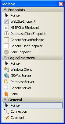
Figure 5-1
Logical datacenter designer toolbox
Connecting EndpointsOnce the users have added hosts to the diagram, they need to be connected to indicate which communication pathways exist. This can either be via the connection tool from the toolbox-by dragging and dropping it between the two ports (endpoints)-or by right-clicking one of the hosts, select Connect, and then choosing the corresponding host to connect it to. The various endpoint client types include:
DatabaseClientEndpoint.
A consumer of a database connection
GenericClientEndpoint.
A consumer of a nonspecific connection
GenericServerEndpoint.
The provider side of a nonspecific connection
HTTPClientEndpoint.
The consumer side of an HTTP connection
WebSiteEndpoint.
The provider/server side of an HTTP connection
ZoneEndpoint.
A communication endpoint on the edge of a zone
Figure 5-2 shows a zone containing an IIS Web server that has the properly configured and connected endpoints.
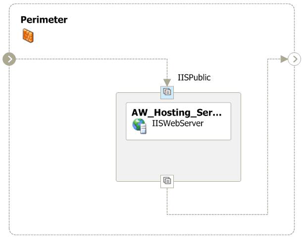
Figure 5-2
An example of a logical datacenter diagram containing a zone
As organizations create and configure clients, servers, and
zones, they might find that they want to reuse the same hosts on other
diagrams. This makes sense, especially when they have a standard configuration
for IIS Web servers, with a specific version of Windows,
Visual Studio can save the reusable host as a logical datacenter designer prototype file (.lddprototype), and later, when editing a diagram, users can locate the new host under the Logical Servers section in the toolbox and drag it onto the design surface. It will have all the same settings and constraints that it was given initially, and can be changed to suit the new datacenter, if need be.
The solution architect's primary task is to define the application's architecture, including its applications, services, and communication pathways. Using Visual Studio, the architect will define the metadata and configuration settings by using the Application Designer. Specifically, this means defining the following characteristics:
Types of applications (applications/consumers, services, or databases)
Communication pathways between applications (connections and endpoints)
Constraints and settings
The Application Designer's focus is assisting in the development of SOA applications. This means that architects are primarily modeling ASP.NET Web services and the applications that consume them.
Application diagrams (and system diagram) can be created before any coding has started. This allows solution architects, who may not be involved with the detailed implementation of a system to use Visual Studio 2005 Team System to work on the design ahead of time. Designing these diagrams before application development gets underway allows the application architecture to be vetted against the logical datacenter diagram to ensure that it will deploy; issues caught early with the architecture are easier and less costly to fix if coding has not yet started. And once a design has been validated the Application Designer will generate a skeleton implementation, with projects, code and configuration files that precisely match the design.
The various types of applications that can be added to diagrams include:
Applications
can include Windows, Microsoft Office, ASP.NET Web applications, external
databases and generic appl
Users work with the Application Designer by dragging prototypes onto the design surface and connecting the resulting application definitions to define the connected system that they are constructing.
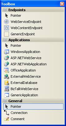
Figure 5-3
Application designer toolbox
Some
of these base application types, such as ASP.NET applications and Windows
applications, support round-trip developing with code, which means that the
application design can be implemented (generated) as code, and that once
implemented, changes made to code are reflected in the designer, while changes
made in the designer are also reflected in code. This is a great development
feature, especially when the architect and developer are two separate
people-things can still stay in synch.
Users can also load additional application types and prototypes that might be supplied by Microsoft or third parties, or create own custom types and prototypes. This capability will be provided by the extensibility tools, which will eventually be made part of the software development kit (SDK).
Applications
communicate through endpoints and can support a Web Application, Web Service or
a generic endpoint. For two applications
to be connected, there must be a provider endpoint at one end of the connection
and a consumer endpoint at the other end. Users can add additional provider
endpoints directly to applications that
There are three application endpoint types, each of which has provider and consumer forms:
WebServiceEndpoint.
That describes a SOAP-based Web service endpoint.
WebContentEndpoint.
That describes an http-based web content endpoint, at which files other than web services will be accessible.
DatabaseEndpoint.
That defines a connection to a database.
GenericEndpoint.
An endpoint of unspecified protocol.
As users create and configure applications, they might find that they want to reuse the same or similar application definition in other solutions. Perhaps they have an standard configuration for an ASP.NET application or maybe a standard set of operations that all Web services should offer. If this is the case users can create their own "custom" prototypes in the toolbox from any application, group of applications, endpoint or group of endpoints that have already been configured on the design surface. Note that this form of reuse is based on propagating a copy of the application or endpoint specifications, and is very different to reusing an application implementation complete with code. An implemented application can be reused by including it in multiple systems. Systems are not intended to be used in other application diagrams but to serve as an efficient way to deploy many related applications together.
The word implement, usually envisions the process of adding all the code to the class so that it's complete, can be compiled, and can be used by the application. In other words, implementing a class means to construct it. Therefore, it would be safe to say that while the solution architect architects a Web service, it's the developer who implements it.
In practice, it's the architect who gets to use the
"implement" feature in VSTS. They can right-click on a Windows application, Web
application, Web service, or Office application and VSTS will generate the stub
code. VSTS also
By default, the implementation provides a skeletal structure, or stub code that is generated - enough for the architect to take a cursory look, change a few namespaces, reference assemblies, add comments, and then send it on its way to the developers. Figure 5-5 shows the new project that gets created.
VSTS will also create a System Definition Model (.SDM)
document and associate it with the newly created project. This document
describes the ASP
All application hosts and applications placed on the logical datacenter diagrams, application diagrams, and system diagrams can have settings and constraints. Constraints define requirements that must be satisfied during deployment - constraints can be set on an application which constrain the logical server on which it can be hosted, can be set on a logical server in which case they constrain the applications that can be deployed to that server. Individual elements in a logical datacenter diagram, for example, can be restricted in many ways to properly model the policies that exist in the datacenter. A constraint might require or restrict certain types of communication, might require specific security aspects, or might bar a certain application type altogether.
There are three primary types of constraints:
Implicit.
Based on the element being used
Example-IIS Servers intrinsically
allow only certain file extension mappings. For example if the .soap script map
were removed form the webserver, the web service bound to a web site would not
be
Predefined.
As defined by the designer
Example-a constraint controls
whether or not an ASP
User-defined.
Created by authoring one or more settings to form a constraint
Example-Only ASP.NET Web services built by the user named Cory can be hosted on a specific host.
Logical server constraints can also advertise the
capabilities of the server. Predefined constraints can be used to specify the
operating system and the
The Settings and
Constraints Editor is used to define various element attributes included in
each diagram: logical datacenter, application, and system. This is the same
editor used by all the distributed system designers in Visual Studio 2005 Team
Architect. The Settings and Constraints Editor is normally docked below the
bottom edge of the logical datacenter diagram. If it isn't visible, it can be
displayed from any diagram element's context menu.
The System Designer is the third of the distributed system
designers is arguably at the heart of the entire suite of tools. When users deploy a distributed application
system they actually deploy a configuration of applications. The applications they deploy will need to be
configured and connected in a carefully considered way that achieves both the
functional goals of the system and is
Its also important to recognize that a system is not
required to be a fully-self-contained business application. Systems can selectively expose the behavior
of the applications they comprise and so are composable. Systems then can be created as reusable
configurations. Systems can be composed
of applications or other systems allowing the construction of architectures
with nested sub-systems. And while in
this first release the System Designer is better suited to bottom-up
composition, it also
The Deployment Designer is the fourth and final architect designer. This designer will allow users to perform a trial deployment, which is to say that this is where they will validate the deployment of the application against a logical datacenter. During this process, settings and constraints will either fit together nicely or clash and generate error messages.
To create a deployment diagram, users must have a completed application diagram and at least one logical datacenter diagram completed as well.
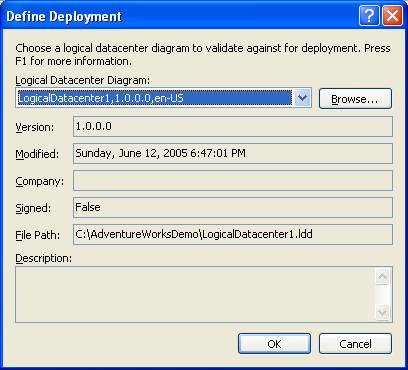
Figure 5-4
Defining a trial deployment
Using
the deployment designer is quite easy. Users just drag an application from the
System View, which provides a list of all the applications in the application
diagram, onto the logical datacenter, dropping it onto a host. Repeat this
process until all the applications are bound. Figure 5-9 shows the deployment
designer with two of the three applications bound to the public and private IIS
server hosts, respectively. Only the wsReview ASP
The designer will provide visual feedback via tooltips that indicate the compatibility of the application on the logical server. This guides the user to appropriately bind the application to correct server. The feedback checks for compatible endpoints (communication capabilities), and hosting restrictions enabled by the LDD.
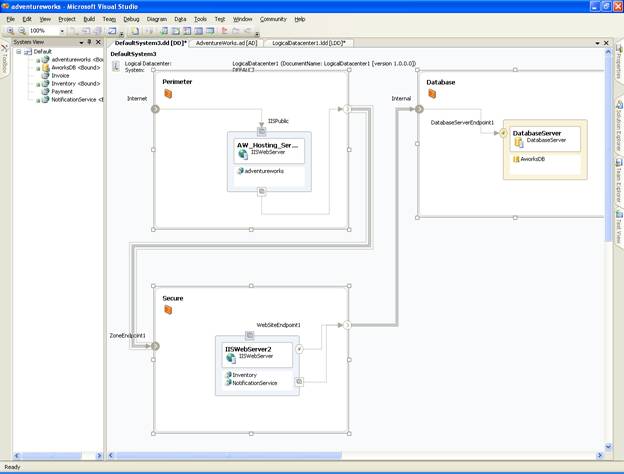
Figure 5-5
Binding applications to a host
Much of the deployment validation is done as users are
dragging and dropping applications from the System View window onto the logical
datacenter designer surface. Right away, the simple communication rules are
enforced. For example, if a users tries to drag an application that requires
HTTP access onto a host that doesn't
Deeper constraint violations won't be apparent until a validation is performed. Remember that much finer policies can be created using the Settings and Constraints Editor, in both the logical datacenter and application designers. Individual elements in the diagrams can be provided with constraints that further restrict the behavior and capabilities of applications deployed in the datacenter. These constraint violations won't surface as they are dragged and dropped, but they will occur later when they are actually validated to the diagram.
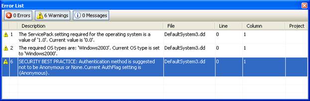
Figure 5-6
Deployment errors and warnings
In the initial version of Visual Studio 2005 Team System, the deployment report is an XML document, which can serve whatever purpose the team might have. It can be transformed or used as input for some other process. VSTS also generates an HTML report for reference containing the following information:
Inventory of all systems, including names and types
Resources for each of the systems,
including assemblies, .exe's, directories, resource files, endpoints, and web.config files
Server settings, including versions, domain controller, terminal server, IIS settings, application pools, .NET versions, and GAC settings
Embedded diagrams (optional)
The report serves as a simple bill of materials report for the deployment team. It enumerates all the servers and services. Beyond containing some simple graphics, the report is fairly static. Figure 5-7 shows an example of the report as it is in XML format. Figure 5-8 shows the same report as HTML, suitable for presentation and communication with ITPros and Architects.
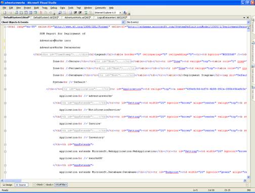
Figure 5-7
Sample deployment report (XML)
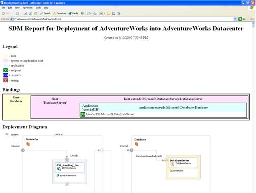
Figure 5-8
Sample deployment report (HTML)
Both the XML and HTML documents are generated from the trial deployment created using the deployment designer. VSTS provides architects with some options when generating the report, such as including the diagrams, owners, binaries, source code, and other content files. When generated, all these files are copied to a specified folder, maintaining a structure of all the files.
With each of these designers, the important data that gets communicated is really about the configuration, constraints, and services required by the datacenter and the applications. With Microsoft's extensibility SDK, and which will be made available in the VSIP SDK, users will be able to model just about anything that they need, including new hosts, caching equipment, etc. Existing servers or hosts-such as IIS, Windows, or SQL-can also be extended by adding new resources (settings that model a particular service or simply a group of settings that communicate specific configuration that a pre or post development process might leverage).
|
Politica de confidentialitate | Termeni si conditii de utilizare |

Vizualizari: 1007
Importanta: ![]()
Termeni si conditii de utilizare | Contact
© SCRIGROUP 2025 . All rights reserved