| CATEGORII DOCUMENTE |
| Arhitectura | Auto | Casa gradina | Constructii | Instalatii | Pomicultura | Silvicultura |
Dimensionarea elementelor de otel/aluminiu
In programul Robot Millennium poate fi executata dimensionarea elementelor structurilor metalice, in concordanta cu mai multe coduri de proiectare. Lista celor disponibile in program este urmatoarea:
Codul american LRFD si LRFD (editia noua)
Codul american ASD
Codul american EIA
Codul canadian CAN/CSA-S16.1-M89
Codurile engleze BS 5950 si BS 5950:2000
Eurocodul 3 (sunt disponibile urmatoarele documente nationale de aplicare): franceze, engleze, germane, belgiene, olandeze, suedeze si finlandeze
Codul francez CM66
Codul francez Add80
Codul olandez NEN6770/6771
Codul
italian
Codul sud-african SABS 0162-1:1993
Codul german DIN 18800
Codul spaniol MV 103-1972 (NBE EA-95)
Codul suedez BSK 99
Codul norvegian CNS 34.
Codul rus SNiP-II-23-81.
In program este disponibil si codul francez Al76 de dimensionare a elementelor structurilor de aluminiu. Metoda de dimensionare a elementelor acestui tip de structuri este identica cu metoda utilizata la dimensionarea elementelor structurilor de otel.
Procesul de dimensionare a structurii este divizata in trei etape. Mai intai, este definita geometria structurii si incarcarile aplicate acesteia; apoi, sunt calculate fortele interioare (tensiunile si eforturile) precum si deplasarile; in final, sunt dimensionate si verificate succesiv elementele structurii in raport cu cerintele de proiectare ale codului. Dimensionarea poate fi realizata pentru elemente independente sau pentru grupuri de elemente, intr-o maniera similara.
In functie de codul de proiectare selectat, continutul listei de parametri definiti inainte de dimensionarea elementelor poate sa varieze, dar principalele definiri sunt aceleasi, independent de aceasta selectie.
Se utilizeaza urmatoarele definitii:
|
ELEMENT (BARA) |
Element independent de tip bara, care urmeaza sa fie verificat sau modificat in acest modul. Cele mai comune tipuri de bare sunt stalpii, grinzile, panele, contravantuirile. O bara utilizata in timpul verificarii/dimensionarii poate fi definita ca element independent sau ca o secventa de elemente consecutive, ce alcatuiesc un stalp, o grinda, etc. |
|
GRUP |
Lista de bare. Un grup de bare structurale carora le va fi atribuita aceeasi sectiune. De indata ce verificarea/dimensionarea este completa, va fi selectata o sectiune corespunzatoare tuturor barelor din grup (in mod independent de diferentele privind valorile eforturilor interne din bare sau a parametrilor de proiectare). Grupurile sunt definite in vederea limitarii varietatii de sectiuni din structura proiectata. |
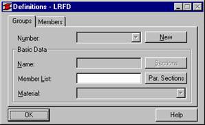
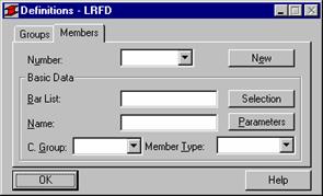
La selectarea tabloului DIMENSIONARE OTEL/ALUMINIU, ecranul va fi divizat in trei parti: vizualizatorul grafic pentru prezentarea structurii si doua ferestre de dialog: Definire si Calcule
Fereastra de dialog Definire contine doua tablouri: Grupuri si Bare (vezi figura de mai jos). La optarea pentru bare sau grupuri, se va realiza verificarea unei singure bare, respectiv a unui grup de bare. Efectuarea unui clic pe butonul Parametri din tabloul Bare conduce la deschiderea ferestrei de dialog Parametri (continutul acesteia depinde de codul de proiectare a otelului selectat). In aceasta fereastra de dialog, pot fi precizati parametrii de cod cum ar fi lungimea de flambaj, parametrii flambajului, parametrii flambajului lateral, etc., in functie de codul de proiectare selectat (vezi figura de mai jos).
|
|
|
Printre cele mai interesante optiuni din programul Robot, se numara si posibilitatea de dimensionare automata prin utilizarea sectiunilor variabile parametrizate. Optiunea devine disponibila prin efectuarea unui clic pe butonul Sectiuni parametrizate localizat in fereastra de dialog Definiri. Optiunea este disponibila atat pentru sectiuni de otel cat si pentru sectiuni de lemn. Forma ferestrei de dialog depinde de materialul selectat pentru dimensionarea barei (otel sau lemn). Utilizatorul are la dispozitia sa doua tipuri de sectiuni (selectia principala este realizata in campul Tipul sectiunii din partea dreapta a ferestrei de dialog):
|
Sectiuni de otel |
Sectiuni de lemn |
|
|
|
Campul Definirea sectiunii din fereastra de dialog Pectiuni parametrizate permite precizarea dimensiunilor sectiunilor de otel sau de lemn. Pentru a lansa proiectarea unei noi sectiuni, se va efectua un clic pe butonul Noua. Va apare o linie noua, in care vor trebui introduse principalele dimensiuni. Efectuarea unui clic pe butoanele Suprima si Suprima totul va duce la stergerea sectiunii selectate, respectiv la stergerea tuturor sectiunilor din lista. Exista doua tipuri de sectiuni:
sectiuni variabile (dH)
sectiuni variabile (auto).
In afara acestora, este disponibil si tabloul Sectiune compusa, ce permite definirea barelor cu sectiune compusa (alcatuita).
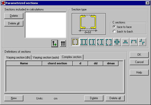
Fereastra de dialog ofera noua tipuri de sectiuni compuse, utilizate cel mai frecvent (sectiunile sunt selectate in campul Tip sectiune din partea dreapta a ferestrei de dialog):
![]() - sectiuni alcatuite din doua
profile C
- sectiuni alcatuite din doua
profile C
![]() - sectiuni alcatuite din doua profile I
- sectiuni alcatuite din doua profile I
![]() - sectiune alcatuita dintr-un profil C si unul I
- sectiune alcatuita dintr-un profil C si unul I
![]() - sectiune alcatuita din doua profile L si un profil I
- sectiune alcatuita din doua profile L si un profil I
![]() - sectiune alcatuita din patru profile L, asezate fata in fata
- sectiune alcatuita din patru profile L, asezate fata in fata
![]() - sectiune alcatuita din patru profile L, asezate spate in spate
- sectiune alcatuita din patru profile L, asezate spate in spate
![]() - sectiune alcatuita din doua profile L, asezate in forma de 'T'
- sectiune alcatuita din doua profile L, asezate in forma de 'T'
![]() - sectiune alcatuita din doua profile L, asezate in forma de 'C'
- sectiune alcatuita din doua profile L, asezate in forma de 'C'
![]() - sectiune alcatuita din doua profile L, asezate in forma de cruce.
- sectiune alcatuita din doua profile L, asezate in forma de cruce.
Definirea unei familii de sectiuni compuse
Pentru a defini o familie (un grup) de sectiuni compluse, utilizatorul trebuie sa parcurga urmatorii pasi:
sa specifice un nume in campul Nume (programul va sugera in mod automat un nume pentru sectiunea complexa)
in campul Forma sectiunii sa defineasca sectiunea initiala cu care va incepe generarea familiei de sectiuni compuse; dupa selectarea acestui camp, programul deschide in mod automat fereastra de dialog Selectarea sectiunii in care trebuie selectata o forma de sectiune din orice baza de date privind sectiunile
sa specifice spatiul initial dintre componentele sectiunii compuse - in campul de editare d si incrementul acestei spatieri - in campul de editare dd; pentru a defini o spatiere maxima, utilizatorul trebuie sa introduca o valoare in campul de editare dmax.
Trebuie reamintit aici faptul ca fereastra de dialog de mai sus este utilizata pentru definirea procedurii de generare a noilor familii de sectiuni compuse. Generarea actuala de familii de sectiuni are loc in procesul de dimensionare al grupului de bare, prin utilizarea familiilor parametrizate definite.
OBSERVATIE: Anumite tipuri de sctiuni (de exemplu, cele alcatuite din 4 corniere) necesita definirea a doua tipuri de sectiuni si a doua spatieri diferite, in functie de planul de contravantuire (b,d).
In cazul sectiunilor din lemn, utilizatorul are la dispozitie si optiunea invariabila. Pentru ca sectiunea definita sa fie recunoscuta in calcule, trebuie ca ea sa fie "mutata" in campul Sectiuni recunoscute in calcul.
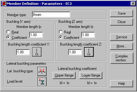
Un exemplu de fereastra de dialog Parametri, in cazul codului de otel LRFD este prezentat in figura de mai jos. Numele tipului de bara selectat este furnizat in campul tipului de bara (poate fi introdus orice nume). Lungimea barei poate fi precizata in campurile: Lungime bara Iy sau Iz. Exista doua posibilitati de definire:
la selectarea optiunii Reala, valoarea introdusa aici este interpretata ca lungime
la selectarea optiunii Coeficient, valoarea este interpretata ca si coeficientul cu care trebuie inmultita lungimea actuala pentru a obtine lungimea reala; prin urmare, introducerea valorii 0.25 va insemna ca lungimea reala reprezinta 1/4 din lungimea actuala.
In campul Coeficientul lungimii de flambaj, pot fi precizate lungimile de flambaj pe ambele directii. Lungimea actuala a unei bare (sau, suma lungimilor elementelor componente) vor fi introduse in mod automat in campurile corespunzatoare.
Coeficientul lungimii de flambaj depinde de conditiile de rezemare de la capetele barei, in planul de flambaj. Lungimea de flambaj a unei bare poate fi precizata si in fereastra de dialog Diagrame de flambaj , care poate fi deschisa prin efectuarea unui clic pe iconita ce reprezinta tipul selectat de model de flambaj al barei. Aici se gasesc modelele tipice de flambaj; de indata ce unul dintre acestea este selectat, valoarea coeficientului ce corespunde acestuia va fi acceptata sau calculata in mod automat.
Prezenta versiune a
programului permite definirea parametrilor contravantuirilor care reduc
lungimea de flambaj (in ambele directii) si lungimea de flambaj lateral (in mod
separat, pentru talpa superioara si cea inferioara). Datorita acestui fapt, in
timpul analizei, se vor putea citi cu o mai mare usurinta seturile de momente
incovoietoare din punctele caracteristice ale barei. Optiunile disponibile in
program permit si definirea coeficientilor lungimilor de flambaj si/sau a
coeficientilor lungimii de flambaj lateral a segmentelor dintre contravantuiri.
Optiunea devine disponibila prin efectuarea unui clic pe iconita ![]() din fereastra de dialog Diagrame de flambaj.
din fereastra de dialog Diagrame de flambaj.
|
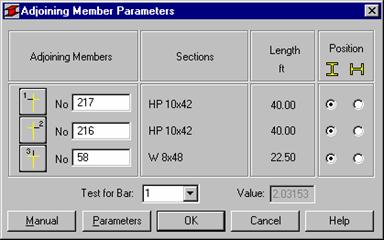
Programul ofera chiar si posibilitatea de a defini coeficientul de flambaj al barei principale, pe baza parametrilor barelor invecinate. Aceasta optiune este disponibila prin efectuarea unui dublu clic pe una din iconitele: localizate in fereastra de dialog Diagrame de flambaj. Parametrii barelor invecinate pot fi precizati in fereastra de dialog alaturata (in cazul prezentat, pentru trei bare invecinate). |
|
In fereastra de dialog de mai sus, pot fi introduse informatiile esentiale privind barele invecinate cu bara principala. In campurile corespunzatoare vor trebui furnizate urmatoarele valori privitoare la bara principala:
numarul barei consecutive a structurii (in cea de-a doua coloana, va fi introdusa in mod automat sectiunea barei selectate a structurii); utilizatorul va trebui sa tasteze numarul barei in campul de editare corespunzator sau sa realizeze o selectare grafica de pe ecran.
pozitia (plasarea) barei
in structura; sunt posibile doua situatii: o sectiune plasata vertical ![]() sau o sectiune plasata orizontal
sau o sectiune plasata orizontal ![]()
In cazul anumitor coduri de proiectare (ADD8, Eurocod 3, NEN6770/6771) mai exista inca un parametru: metoda de rezemare a celeilalte extremitati a barei alaturate. Tipurile de reazeme disponibile depind de cerintele codului de proiectare a otelului selectat.
Programul ofera si posibilitatea de a preciza manual parametrii barelor alaturate. In fereastra de dialog respectiva, acesti parametri vor putea fi introdusi manual.
In campul Parametrii flambajului lateral, pot fi selectate optiunile utilizate la verificarea la flambaj lateral: tipul de flambaj lateral, nivelul de incarcare si coeficientul lungimii de flambaj lateral. Efectuarea unui clic pe iconita corespunzatoare deschide fereastra de dialog pentru definirea parametrilor aferenti.
Optiunea Tipul de flambaj lateral este utilizata pentru definirea parametrilor de cod ai flambajului lateral, depinzand de modelul static al barei. In concordanta cu cerintele de cod, poate fi acceptat unul din modelele considerate de catre cod. Modelele din forma iconitelor reprezinta pozitiile corespunzatoare ale reazemelor din cod. Efectuarea unui clic pe ultima dintre iconite, va conduce la neincluderea efectelor flambajului lateral in calcule.
Pentru o calculare corecta a coeficientului de flambaj lateral, este necesar sa se stabileasca lungimea de flambaj lateral. Datorita posibilitatii de fixare independenta a talpii superioare si inferioare si de aparitie a unor stari de tensiune semnificative in ambele, sunt disponibile doua lungimi de flambaj lateral. Acestea sunt controlate de catre un coeficient, cu care lungimea de baza trebuie multiplicata pentru a se obtine lungimile de flambaj lateral reale. Lungimea Iz este considerata ca lungime de baza. Valoarea coeficientului poate fi introdusa direct sau poate fi selectata o iconita a tipului de caz de rezemare, din care acest coeficient va fi obtinut in mod automat.
La efectuarea unui clic pe butonul Alte, pe ecran va apare o alta fereastra de dialog, in care se pot defini parametrii incarcarii si ai sectiunii. La efectuarea unui clic pe butonul Service, apare o fereastra de dialog in care se poate specifica o valoare acceptabila a deplasarii.
Dupa efectuarea unui clic pe butonul Sectiune compusa, programul va prezenta o alta fereastra de dialog, Sectiune compusa in care pot fi precizati parametrii sectiunii compuse (vezi capitolul 3).
Numele barei selectate este oferit in campul Tip bara. Lungimea barei va trebui furnizata in campurile Lungimea barei ly sau lz.
|
Acest lucru poate fi realizat in doua moduri: la selectarea optiunii Reala, valoarea introdusa este interpretata ca lungime la selectarea optiunii Coeficient, valoarea introdusa este interpretata ca si coeficientul cu care trebuie multiplicata valoarea actuala pentru a obtine lungimea reala. De exemplu, introducerea valorii de 0.25 va insemna ca lungimea reala reprezinta 1/4 din lungimea actuala. |
|
Pentru definirea simultana a catorva bare, avand dimensiuni actuale diferite, cu reazeme egal departate, cea de-a doua metoda mentionata este foarte convenabila. In cazul in care se doreste salvarea setului de parametri ca si o categorie, introducerea lungimii in acest mod este esentiala. Coeficientul lungimii de flambaj depinde de conditiile de rezemare in planul de flambaj, din nodurile barei. Lungimea de flambaj poate fi precizata si in fereastra de dialog Diagrame de flambaj, care se deschide la efectuarea unui clic pe una din iconitele ce reprezinta tipul de mod de flambaj selectat. Aici pot fi gasite modurile tipice; de indata ce unul dintre acestea este selectat, valoarea coeficientului va fi acceptata sau calculata in mod automat.
Iconitele din fereastra de dialog pot fi divizate in doua grupuri: primul grup contine metodele tipice (de cod) de rezemare a unei bare si valorile corespunzatoare ale coeficientilor lungimii de flambaj, in timp ce cel de-al doilea contine iconitele optiunilor utilizate pentru calcularea coeficientilor de flambaj ai stalpilor cadrelor multi-etajate. Culorile iconitelor reprezinta: rosu (A) - calcule pentru cadre fixate lateral, albastru (B) - pentru cadre nefixate lateral.
Flambajul este luat in considerare in calcule in cazul in care apare o forta de compresiune in bara, chiar si in cazul in care aceasta forta are o valoare neglijabila fata de a celorlalte eforturi. Programul nu realizeaza singur analize pentru a stabili daca efectele flambajului trebuie sau nu luate in considerare. In cazul in care utilizatorul doreste sa elimine efectele flambajului din calcule, va trebui selectata ultima dintre iconite, care va conduce la ignorarea flambajului in calcule.
|
Optiunile utilizate la verificarile la flambaj lateral: parametrii Lb si Cb, care pot fi selectati in campul Parametrii flambajului lateral. Efectuarea unui clic pe iconita ce corespunde parametrului Cb deschide fereastra de dialog pentru precizarea parametrilor corespunzatori. In fereastra de dialog alaturata, trebuie selectate optiunile de calcul pentru barele sau grupurile de bare de otel. Campul Optiuni de verificare permite utilizatorului sa selecteze: |
|
Verificarea unei bare - verificare in concordanta cu lista de bare, bazata pe calculele consecutive si independente ale fiecarei bare. Procedura este bazata pe considerarea unor puncte intermediare pe lungimea barei incarcate si pe verificarea faptului ca aceasta este indeplineste conditiile celor mai importante coduri, in cel mai dur dintre cazurile de incarcare. Trebuie ca in calcul sa fie luat in considerare un numar de puncte si specificata o lista a cazurilor de incarcare. Cu alte cuvinte, verificarea este bazata pe a examina daca anumite sectiuni (acceptate inainte de calculul eforturilor) indeplinesc cerintele codurilor. Selectia va specifica barele considerate satisfacatoare, nesatisfacatoare sau instabile.
Verificarea unui grup - verificarea grupului este bazata pe calcule consecutive si independente (vezi Verificarea unei bare) pentru fiecare bara din grup. Sunt luate in considerare proprietatile de material ale grupului.
Dimensionarea unui grup - dimensionarea grupului este bazata pe examinarea setului de sectiuni adoptate anterior, precizate prin Definirea Grupului si eliminarea acelora care nu indeplinesc cerintele de cod. La gasirea primei sectiuni care indeplineste cerintele de cod sectiunile consecutive sunt eliminate (luand in considerare optiunile de optimizare pot fi realizate calcule ale grupului de bare). Descrierea procesului este condusa separat, pentru fiecare familie de sectiuni ce apartine grupului analizat. Calculele de cod sunt realizate pentru fiecare sectiune in punctele intermediare consecutive, pentru cazurile consecutive de incarcare, elementele consecutive ale barei date si ale tuturor barelor care apartin grupului. In cazul in care sectiunea nu indeplineste cerintele codului pentru unul din punctele intermediare, cazul de incarcare sau elementul barei din grup este eliminat si din lista va fi selectat elementul urmator. Acest proces continua pana in momentul in care toate sectiunile din lista sunt eliminate. Pentru lansarea calculelor in modul de dimensionare, trebuie precizat cel putin un grup. Dimensionarea poate fi condusa pentru mai multe grupuri (procesul este realizat pentru fiecare grup, in mod separat).
In cazul in care optiunea Optimizare este activata si se efectueaza un clic pe butonul Optiuni, pe ecran apare fereastra de dialog suplimentara Optiuni de optimizare, care permite selectarea urmatoarelor optiuni de optimizare in timpul calculelor barelor din grup:
greutate - bifarea acestei optiuni va duce la luarea in considerare in procesul de optimizare a greutatii (masei) barei sectiunii; acest lucru inseamna ca programul va cauta in grupul de sectiuni care indeplinesc criteriile definite ale codului sectiunea cea mai usoara
inaltime maxima a sectiunii - bifarea acestei optiuni va duce la luarea in considerare in procesul de optimizare a inaltimii maxime a grinzii; utilizatorul poate preciza inaltimea sectiunii in campul de editare localizat in dreapta optiunii
inaltime minima a sectiunii - bifarea acestei optiuni va duce la luarea in considerare in procesul de optimizare a inaltimii minime a grinzii; utilizatorul poate preciza inaltimea sectiunii in campul de editare localizat in dreapta optiunii
grosime minima a talpii - bifarea acestei optiuni va duce la luarea in considerare in procesul de optimizare a grosimii minime a talpii; utilizatorul poate preciza grosimea talpii in campul de editare localizat in dreapta optiunii
grosime minima a inimii - bifarea acestei optiuni va duce la luarea in considerare in procesul de optimizare a grosimii minime a inimii; utilizatorul poate preciza grosimea inimii in campul de editare localizat in dreapta optiunii
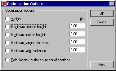
Partea inferioara a ferestrei de dialog contine optiunea Calcule pentru intregul set de sectiuni. Bifarea acesteia duce la activarea in timpul calculului a procedurii de cautare, in intreaga baza de date, a sectiunii optime (acest lucru este foarte important atunci cand baza de date contine sectiuni care nu sunt aranjate in ordine crescatoare, astfel incat o sectiune data sa fie mai mare decat cea precedenta).
In cazul in care optiunea Calcule pentru intregul set de sectiuni este activata, iar optiunea Greutate (masa) este dezactivata, sectiunea optima va fi cea pentru care valoarea coeficientului de eficienta va fi mai mare (dar inferioara lui 1).
Partea inferioara a ferestrei de dialog Calcule contine butonul Configurare. Efectuarea unui clic pe acesta va duce la deschiderea ferestrei de dialog Configurare , utilizata la precizarea parametrilor ce vor fi utilizati in timpul verificarii unei bare de otel. In fereastra de dialog pot fi precizati urmatorii parametri de calcul:
punctele de calcul; acestea pot fi precizate in urmatoarele doua moduri:
prin precizarea unui numar de puncte de-a lungul lungimii barei (punctele fiind distribuite uniform pe lungimea barei) - optiunea Numar de puncte
prin precizarea coordonatelor punctelor caracteristice; pentru a realiza acest lucru, trebuie mai intai activata optiunea Puncte caracteristice, si apoi efectuat un clic pe butonul Optiuni; aceasta va duce la deschiderea ferestrei de dialog Calcule in puncte caracteristice (punctele cu valori maxime ale eforturilor, etc.)
factorul de eficienta defineste coeficientul cu care va fi inmultita limita rezistentei plastice (cresterea/scaderea limitei de plasticitate)
zveltetea maxima; la activarea acestei optiuni, va fi verificata zveltetea barei. Mai mult decat atat, poate fi precizata o valoare admisibila a zveltetii barei.
In partea mediana a ferestrei de dialog pot fi selectate eforturile care vor fi luate in considerare in calculele de cod ale barei; bifarea unei optiuni (de exemplu, Fx) va conduce la luarea in considerare a efortului Fx. Mai mult chiar, pot fi selectate unitatile in care vor fi prezentate rezultatele in procesul de dimensionare a barei. Rezultatele pot fi prezentate in unitatile utilizate in codul de otel indicat, sau in unitatile sistemului Robot.
Partea inferioara a ferestrei de dialog contine lista de selectare a cazului de incarcare (incarcare moarta), pentru care deplasarile definite vor fi tratate ca sageti initiale ale structurii. In acest caz, trebuie ca optiunea Luarea in considerare a sagetilor din urmatorul caz de incarcare sa fie activata.
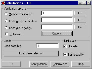
Partea inferioara a ferestrei de dialog Calcule contine doua campuri: Incarcari si Stare limita. In primul dintre acestea, sunt localizate urmatoarele optiuni:
lista cazurilor de incarcare - camp pentru afisarea cazurilor de incarcare ce vor fi luate in considerare in timpul calculelor. In acesta poate fi introdus numarul cazului de incarcare.
Selectarea cazului de incarcare - deschide o fereastra de dialog suplimentara (Selectarea cazului) in care pot fi precizate cazurile de incarcare ce vor fi luate in considerare in timpul calculelor.
Calculele pot fi rulate in ULS (Stari Limita Ultime) si SLS (Stari Limita ale Exploatarii Normale).
Efectuarea unui clic pe butonul Calcule conduce la verificarea sau dimensionarea barei de otel, in concordanta cu parametrii precizati in ferestrele de lialog Definire si Calcule. De indata ce calculele au fost efectuate, pe ecran va apare fereastra de dialog Rezumat al rezultatelor. Fereastra de dialog consta in doua tablouri: Rezultate si Mesaje. Cel din urma prezinta informatii clare privind avertismente si erori aparute in timpul verificarii/dimensionarii barei structurii. Efectuarea unui clic pe lista scurta din tabloul Rezultate va duce la afisarea ferestrei de dialog Rezultate.
Aici trebuie mentionate cateva diferente dintre afisarile de rezultate ale variatelor optiuni de calcul:
Verificari ale listei de bare - este afisata doar o
singura linie pentru fiecare bara sau pentru fiecare grup de bare, in
concordanta cu lista de bare sau de grupuri de bare. Sectiunile care
indeplinesc cerintele de cod sunt marcate cu simbolul ![]() , in timp ce cele care nu le respecta sunt
marcate cu simbolul
, in timp ce cele care nu le respecta sunt
marcate cu simbolul ![]()
Dimensionarea grupului de bare - sunt afisate trei sectiuni consecutive din
fiecare familie a grupului de sectiuni selectat. Sectiunea din linia centrala
indeplineste cerintele codului. Numele de sectiuni precedate de catre
simbolurile ![]() si
si ![]() indica acele sectiuni transversale care fie nu
indeplinesc cerintele de cod, fie le indeplinesc cu o rezerva excesiva. Profilele
care indeplinesc cerintele de cod sunt marcate cu simbolul
indica acele sectiuni transversale care fie nu
indeplinesc cerintele de cod, fie le indeplinesc cu o rezerva excesiva. Profilele
care indeplinesc cerintele de cod sunt marcate cu simbolul ![]() , in timp ce cele care nu le indeplinesc sunt
marcate cu simbolul
, in timp ce cele care nu le indeplinesc sunt
marcate cu simbolul ![]() . Sectiunile instabile sunt marcate cu ajutorul
uneia dintre iconitele urmatoare:
. Sectiunile instabile sunt marcate cu ajutorul
uneia dintre iconitele urmatoare: ![]() sau
sau ![]() . Prima este aplicata
barei sau grupului de bare instabile, in timp ce cea de-a doua indica o bara
sau un grup de bare instabile, al carui factor de eficienta este mai mare decat
1.0.
. Prima este aplicata
barei sau grupului de bare instabile, in timp ce cea de-a doua indica o bara
sau un grup de bare instabile, al carui factor de eficienta este mai mare decat
1.0.
Optimizarea unui grup de bare (optiunea Optimizare
din Dimensionarea unui grup este activa) - continutul ferestrei de dialog Rezumat
al rezultatelor este acelasi ca in cazul dimensionarii grupului. Suplimentar,
la inceputul liniei corespunzatoare, este afisat simbolul ![]() , care indica sectiunea optima (in cazul in
care aceasta exista). Mai jos, este prezentata o
imagine a ferestrei de dialog Rezumat al rezultatelor, pentru
dimensionarea grupurilor de bare, cu optiunea de optimizare activata.
, care indica sectiunea optima (in cazul in
care aceasta exista). Mai jos, este prezentata o
imagine a ferestrei de dialog Rezumat al rezultatelor, pentru
dimensionarea grupurilor de bare, cu optiunea de optimizare activata.
Calculele pot fi conduse si pentru eforturi precizate de catre utilizator (ce nu au fost obtinute de catre program). Acest lucru poate fi realizat utilizand optiunea Calcule manuale, disponibila din meniu Analiza / Dimensionarea unei bare a structurii / Dimensionarea unei bare de otelaluminiu. Poate fi efectuata o verificare/dimensionare a barei.
In figura de mai jos este prezentata o fereastra de dialog cu rezultate simplificate (rezumat).
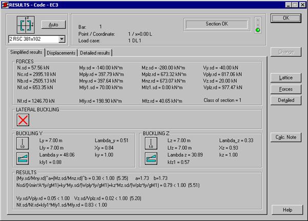
La efectuarea unui clic pe butonul Note de calcul, pe ecran va apare o fereastra de dialog suplimentara. In aceasta, se va putea selecta tipul de note de calcul ce vor fi generate.
|
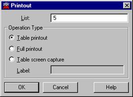
If the Table printout option is selected, the program will print a simple calculation note containing a table with the basic information concerning the designed or verified members or groups of members (the note will be presented in the same form as in the Short results dialog box). On the other hand, if the Full printout option is selected, the calculation note will contain all the code-defined conditions checked during calculations/verification of members or groups of members. The calculation note will be created for selected members or groups of members. The user may select members or groups of members in the List edit field (all members of groups of members are contained in the field by default). |
|
Selecting the Table screen capture option means that the table with the basic information concerning designed or verified members or groups of members - presented in the Short results dialog box - will be screen-captured (the user should define the name of the screen capture in the Label edit field). It will be possible to use the table in printout composition. The name of the table screen capture will be available on the Screen Captures tab in the Printout composition dialog box.
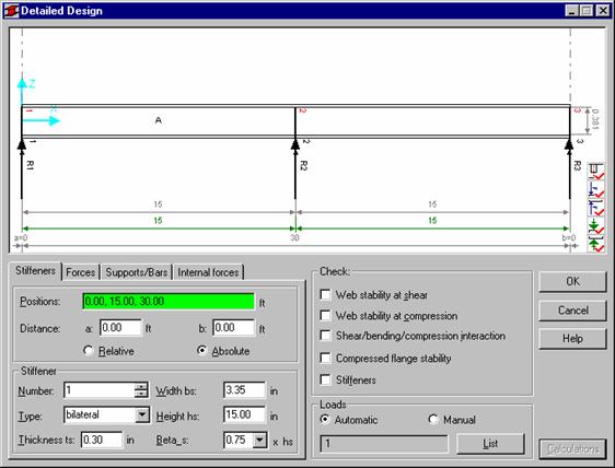
1. Detailed Analysis - Eurocode3
The option allows one to carry out detailed analysis of I-section members, rolled or welded. The detailed analysis of a member can be activated by pressing the Detailed button located in the Detailed results dialog box for the EC3 code.
The program allows one to carry out the following calculations on the basis of the requirements defined in EUROCODE 3:
Web stability for shearing
The program analyzes each panel (the space between neighboring ribs) at 11 points to find the greatest value of the shearing force. For the identified force, the program carries out verification according to paragraph (5.6)
The results are presented for each panel at the points where there appeared the most straining stresses.
Web stability for compression (chapter 5.7 of the code)
Verification of the web under a concentrated force is carried out only when the force is applied to a point where there is no rib (the web is not ribbed)
The program carries out an analysis aimed to determine if the force or reaction results in web compression. The compression effect results from a force (reaction or an adjoining bar) in the following cases:
a force (reaction or an adjoining bar) at the top and the negative force (reaction) value
a force (reaction or an adjoining bar) at the bottom and the positive force (reaction) value
Otherwise, the program does not carry out calculations (the force is disregarded)
Calculations are carried out for all load cases defined by the user in the Automatic loads field
If there are several concentrated forces (within one load case), the program automatically sums them up
In the case of a combination or code combination, if there are several forces originating from different load cases, the program sums them up while recognizing at the same time the relevant combination coefficients
The results are provided for each force that results in compression of the web without ribs.
NTM interaction (chapter 5.6.7 of the code)
The program analyzes each panel at 11 calculation points
Calculations are carried out for all load cases defined by the user in the Automatic loads field
Results are shown for the point of a panel where there appears the most straining stress.
Compressed flange stability (chapter 5.7.7 of the code)
The program verifies compressed flange stability at 3 equidistant points (flange beginning, center and end)
The program checks the geometrical condition of the compressed flange stability according to the formula (5.80).
Transversal ribs stability
The check is carried out at the points where stiffeners are located
If a concentrated force is applied directly to a rib, the force itself will be taken for verification. If no concentrated force is applied directly to a stiffener, the program calculates the force that compresses the stiffener and does so on the basis of formula (5.63). If the concentrated force results in stretching the stiffener, then calculations for the stiffener are not performed
Multiple forces applied to a stiffener are combined in an analogous manner as in the case of concentrated forces applied to a web without stiffeners.
Once the Detailed analysis option is run, the program reads all the concentrated force for the load case that turned out to be decisive during the verification if the member complies with the code. If, for instance, the load case DEAD1 turned out to be most exigent during member verification, then, all the concentrated forces covered by the load case will be read by the program. If, however, a combination or code combination turned out to be decisive, the program will read all the concentrated forces covered by the simple load cases included in the combination. The governing load case is automatically introduced into the Automatic loads edit field. The automatically-recognized concentrated forces are visualized in the graphical viewer, together with the force number and its coordinates. The coordinate system is located by default in member beginning.
A user can verify if the concentrated forces are recognized correctly in the Concentrated forces tab.
The program is set by default in the automatic mode (the Loads / Automatic option). It means that the calculations will recognize the load cases formerly defined by the user. All the external and internal forces will be read for the current load case(s), and only the forces will be recognized during calculations.
If the user wants to introduce a new load case, he must enter the manual mode.
The Detailed analysis dialog box is divided into several parts:
the top part of the dialog box contains a schematic representation of the member containing member dimensions; the following icons are located in the bottom right-hand corner of the drawing:
|
|
switching on/off of the presentation of ribs, rib numbers, panel numbering and distances between ribs |
|
|
switching on/off of the presentation of the forces operating in the top flange of the member, their numbering and the distance between the forces |
|
|
switching on/off of the presentation of the forces operating in the bottom flange of the member, their numbering and the distance between the forces |
|
|
switching on/off of the presentation of supports/adjoining bars located in the top flange of the member, their numbering and the distance between supports/adjoining bars |
|
|
switching on/off of the presentation of supports/adjoining bars located in the bottom flange of the member, their numbering and the distance between supports/adjoining bars |
the part containing four tabs: Stiffeners, Forces, Supports/Bars and Internal forces
the fields Verification and Loads.
The Stiffeners tab
Once the Detailed analysis is run, ribs are calculated automatically at the following member points:
at the points where support have been defined
at the points where concentrated forces have been applied
at the points where adjoining bars have been identified
if the distances between bracings are excessive and do not meet code-defined requirements.
It is possible to modify the parameters of the automatically-defined ribs. All the automatically-defined ribs may be modified, added or deleted at will.
The Forces tab
A user can verify if the concentrated forces are recognized correctly using the Forces tab.
The program is set by default in the automatic mode (the Loads/Automatic option). It means that the calculations will recognize the load cases formerly defined by the user. All the external and internal forces will be read for the current load case(s), and only the forces will be recognized during calculations.
If the user wants to introduce a new load case, he must enter the manual mode. There is no possibility in the automatic mode to change the position of load application along an element, neither is it possible to modify its value.
The Supports/Bars tab
If a user-defined support has been identified in the beam in question, the support will be automatically introduced into the list of supports and drawn in the graphical viewer. During calculations, the program will verify the beam, recognizing the information concerning the reactions in the support.
(NOTE: the assumption is correct, if the reaction is perpendicular to the longitudinal axis of the beam).
For instance, for a beam with pinned supports and a concentrated force P applied at the center, the program will identify two support at beam ends and it will recognize the reaction value R = P/2 in its calculations.
If no supports are defined along the beam, the program will verify if a vertical bar adjoins the beam in question (a bar that may potentially serve as a support). If there is an adjoining bar, the program suggests a support at this point. The value of the reaction transferred to such support will be calculated on the basis of the analysis of the shearing force at this point.
In all other cases, the program suggests by default the position of supports at beam ends.
The program automatically identifies the places where there are adjoining (subordinate) beams, that transfer loads to the beam in question. During calculations, the program finds the force transferred by the bar(s) by analyzing the distribution of the shearing force over the beam in question. For instance, while analyzing a cantilever beam with the load P applied at its end, the force being transferred from a subordinate beam, the program will identify the place where the force has been transferred and calculate the force P on the basis of the shearing force diagram at this point.
The Internal forces tab
In order to define a new load case, one should select the Manual option available in the Loads field. From now on, the user may introduce arbitrary concentrated forces, define ribs in arbitrary locations and determine internal forces, corresponding to the defined load. The values of internal forces should be defined in the Internal forces tab.
If the user has already entered the Manual mode, the calculation will be carried out only for the manually defined load case. It is not possible to run calculations for both an automatically-defined load case and a manually-defined one.
The option enables detailed analysis of webs in I-bars, bars with box-section or channel bars made of rolled or welded sections. The detailed analysis of a bar can be run by pressing the Detailed button in the dialog box with detailed results for the French steel code CM66.
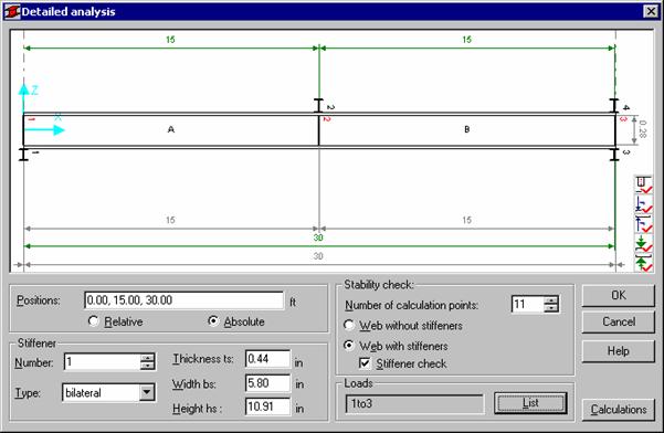
The program allows for the following calculations based on the requirements described in the CM66 code:
stability of web without stiffeners under complex stress (chapter 5,212-3)
stability of web with stiffeners under complex stress (chapter 5,212-3)
stiffener check (chapter 5,212-4).
The stability check of a web with or without stiffeners is performed separately. The stiffener stability may be verified only if the check of web with stiffeners is selected.
The user may carry out analysis of a member at the specified number of calculation points (101 at the maximum). The program checks an appropriate code condition for every point as many times as many load cases (code combinations) have been defined, afterwards, it presents the results for the load case with the greatest ratio.
The dialog box is divided into several parts:
the top part of the dialog box presents a schematic drawing of a member including its dimensions; the bottom right corner of the drawing shows the icons listed below:
|
|
switches on/off display of stiffeners, stiffener numbers, panel numbers and distances between stiffeners |
|
|
switches on/off display of forces acting on the upper flange of a member, their numbers and distances between them |
|
|
switches on/off display of forces acting on the lower flange of a member, their numbers and distances between them |
|
|
switches on/off display of supports/adjoining bars positioned on the upper flange of a member, their numbers and distances between them |
|
|
switches on/off display of supports/adjoining bars positioned on the lower flange of a member, their numbers and distances between them |
The detailed analysis performed for the French steel code CM66 applies load cases defined earlier by the user in calculations. For the current load case or load cases the program will read all the external and internal forces and only them will be taken into account in calculations.
If on an analyzed beam a support defined earlier by the user, has been detected, then it will be drawn automatically in a drawing. If no supports have been defined on a beam (the user is considering e.g. spandrel beam of a frame), the program checks if a vertical bar (which potentially may act as a support) adjoins the analyzed beam. If yes, it suggests that a support should be defined there. The program automatically recognizes the points where adjoining (subordinate) beams are positioned, which transfer loads onto the analyzed beam. Positions of concentrated forces acting on the beam are also recognized automatically.
Calculations are started after pressing the Calculations button.
Below are listed the options contained in the lower part of the dialog box:
Number of calculation points - the field where the user should specify the number of member divisions into segments of equal length; at these points internal forces will be calculated
Web without stiffeners - if this option is selected, then all the options concerned with member stiffeners are unavailable and the member is being analyzed as the one without stiffeners
Web with stiffeners - if this option is selected, then the options concerned with member stiffeners become available (a part of them, after switching the Stiffener check option) and the member is being analyzed as the one with stiffeners
Stiffener check - as soon as this option is switched on, the fields used for definition of basic stiffener parameters become active; each stiffener may be freely modified
Loads - list presenting load cases taken into consideration in the member detailed analysis.
Stiffeners are defined automatically after running the Detailed analysis at the following locations on the bar:
at points where supports have been defined
at points where concentrated forces are applied
at points where adjoining bars have been detected.
Parameters of the stiffeners defined automatically may be changed: all the stiffeners defined automatically may be freely modified, added or deleted. Stiffener positions are shown in the Positions edit field; a stiffener position may be defined in real coordinates or in relative coordinates (with respect to bar length).
By default, the following stiffener parameters are set:
Stiffener type - bilateral
Thickness = web thicknesses
Width = half the difference between beam width and web thickness
Height = web height.
It is assumed by default that length of the beam equals the distance between the theoretical axes of members.
The program enables performing the following calculations:
Stability of web without stiffeners under complex stress (5,212-3)
A beam is being analyzed at the number of points that has been defined by the user in the Number of calculation points edit field
Stresses at the current calculation point are calculated on the basis of internal forces read for a given load case. These stresses are used further on, to check the empirical verification formula given in point 5.212-3
Results are presented for each calculation point and for the load case resulting in the most unfavorable ratio.
Stability of web with stiffeners under complex stress (5,212-3)
The program follows the same pattern as for the check of web without stiffeners. During verification the program applies the second empirical formula given in point 5.212-3
Stability of transversal stiffeners (5,212-4)
The check is run at points where stiffeners are positioned
A force acting on the stiffener is calculated, according to the commentary to point 5,212-4, as a difference between the transversal force acting on the point where the stiffener is positioned and the maximum transversal force that a web without stiffeners is able to carry at this point
Parameters of stiffeners are calculated assuming that they cooperate with the web segment of the length equaling 30-fold thickness of the web.
Stiffener stability is checked analogously as the stability of columns in axial compression, according to point 3,41 of the code.
The option is used to determine parameters of complex members. It is accessible after pressing the Complex section button in the Member Definition - Parameters dialog box.
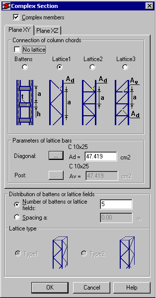
If the Complex members option is switched on, then the program will perform member calculations considering the guidelines for complex members according to point 5.9 of Eurocode 3 or point 4.7 of PN-90/B-03200 code.
In the Distribution of battens or lattice fields field the user may define arrangement of elements connecting individual column chords. It may be done in two ways:
by specifying a number in the Distribution of battens or lattice fields field; the program will automatically distribute battens (lattice fields) evenly over the entire member length; NOTE: battens at supports (extreme battens) are also included in the specified number of battens; for example, if number 4 is defined for the 3-meter long member, then 4 battens will be positioned at the coordinates as follows: ( 0.0 m, 1.0 m , 2.0 m, 3.0 m)
by defining the value of spacing a between individual connecting elements in the Spacing a edit field; it is assumed that values of the batten spacing or the height of all lattice fields are equal over the member length; if the member length is not a whole multiple of the spacing a, the battens are distributed uniformly with respect to the member center: thus definition of spacing a = 1.0 m for a 3.2 m-long member will cause uniform distribution of 4 battens over the member length at the coordinates: (0.1 m, 1.1 m , 2.1 m, 3.1 m).
It has been assumed that the relevant batten (lattice) planes are parallel to the local axes of a complex section (x - member longitudinal axis, y - horizontal axis, z - vertical axis). On the Plane XY tab the user may define types of battens or lattice positioned in the plane parallel to the local y axis. Analogously, the Plane XZ tab is used to define parameters of battens or lattice positioned in the plane parallel to the local z axis. If the No lattice option is activated, then calculations do not account for the fact that this is a complex member and are performed assuming that the chords are a completely integrated whole in a given plane. For Eurocode 3, selection of the Battens option enables definition of the basic batten dimensions (height, thickness). After selecting one of the lattice types (Lattice 1, 2, 3), options allowing definition of lattice bars become accessible. It is assumed, that posts and diagonals are usually made from the same sections. For Eurocode 3, when Lattice 3 is chosen, the user may define different sections for diagonals and posts. Pressing the () button to the right of the Diagonal section option (or the Diagonal / Post options for Eurocode 3) opens the Section selection dialog box where a name of lattice element may be defined. Selection of a section results in its area being entered automatically to the Ad (Av) edit field.
After verification of a complex member there is a possibility to select and verify elements connecting individual member chords. Analysis of chord connections in a complex member is run by pressing the Lattice button in the Detailed Results dialog box. The Connection of Chords dialog box consists of two tabs containing data about connectors in planes XY and XZ needed for calculations. For each of the planes the analysis is carried out independently.
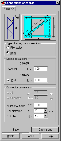
Depending on the earlier defined type of chord connection in individual planes (battens or lattice selected in the Complex Section dialog box) the program automatically proposes the possible solution for connection details.
There are the following analysis types available in the program:
for battens:
welded connection to member: fillet weld
welded connection to member: butt weld
bolted connection to member
for lattice:
welded connection to member: fillet weld
bolted connection to member.
Verification of the chord connection includes resistance check of the element connecting the chords (batten resistance, compression with buckling of diagonals and posts) and resistance check of welds (bolts) connecting battens (lattice) with a member section.
While defining parameters of a batten connection with a column section, verification of basic geometrical parameters of the connection is performed. For a fillet weld connection the program checks allowable dimensions of fillet welds. It is assumed that the fillet weld takes the shape of letter C. If length of horizontal parts of a weld is not greater than 40 mm, then these parts are not considered in calculations (only vertical parts of the weld are considered in calculations).
The program also performs geometrical verification of distribution of bolts in a batten connection and if data is incorrect, a message is displayed on the screen. For the butt weld it is assumed that the weld length equals the batten height, while the thickness is a lesser value of the batten thickness and the thickness of flanges of the column chords.
Verification of a connection of lattice elements with the column section is carried out in a simplified manner. For fillet weld connections, the program requests the total length of welds connecting the lattice with the column section and assumes that the center of gravity of the weld system is colinear with the member axis (the system is subjected only to shear without considering possible eccentricities). For bolted connections it is also assumed that the section axis and the axis of bolt positions are colinear. Therefore, load capacity of such a connection is a total of capacities of all the bolts included in the connection.
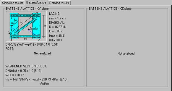
To start calculations of chord connections, the user should press the Calculations button. The Detailed Results dialog box shows the additional tab Battens /Lattice which contains the most important results of connection verification (entire data and all verification results in a table form).
Thus-designed chord connections may be saved together with a member; the Save button is used for that purpose. Thanks to that, after defining the connection of chords in a member, during next verification the user obtains complete results together with the full verification of the connection (without the need to open the Connections of chords dialog box again). Results may be deleted, as well, by pressing the Delete button.
Another assumption is that a set of information about chord connections in a column is unbreakably linked with a specific section and a specific lattice type defined during member parameter definition. If a different section is ascribed to a member or if a lattice definition is modified, then information on chord connections is removed.
The program also provides the possibility of defining chord connections for several members simultaneously. It may be done in two ways:
After group verification:
The result of verification of a member group is indication by the program of the group's representative with the greatest ratio. After opening the Detailed Results dialog box for this member, the user may design a connection of member chords. If the Save button is pressed after designing this connection, then definition of this connection is ascribed to all the members included in the verified group. Take note, however, that it is possible only on condition that for all the members the same section and appropriate lattice types have been defined. From this moment on, verification of all members in a group will be carried out taking account of the chord connection check.
After group design
The result of verification of a member group is indication of the sections among member families defined for calculations, which satisfy the code conditions. After opening the Detailed Results dialog box for a selected section, the user may design a connection of chords.
The designed connection may be ascribed to a member on condition that the currently considered section is simultaneously assigned to the analyzed member group. If the Save button is pressed, then the program will simultaneously ascribe the section together with the chord connection designed for this section to the member group. From this moment on, verification of all members in a group will be carried out while taking account of the chord connection check.
SELECTED REFERENCES (DESIGN OF STEEL STRUCTURES)
AKBAR R. TAMBOLI, Steel Design Handbook - LRFD Method, The McGraw-Hill Companies Inc., 1997
CHARLES G. SALMON, JOHN E. JOHNSON, Steel Structures - Design and Behavior, Third Edition by HarperCollins Publishers Inc., 1990
JEAN MOREL, Calcul des structures metalliques selon l'EUROCODE 3, Eyrolles, 1994
JEAN MOREL, Structures Metalliques - Guide de calcul CM66 - Additif 80 - Eurocode3, Eyrolles, 1999
Steelwork Design Guide To BS5950: PART 1: 1990 - Third Edition, Volume 1 - Section Properties, Member Capacities & Volume 2 - Worked Examples, The Steel Construction Institute in association with: The British Constructional Steelwork, 1992
T J MAC GINLEY & T C ANG, Structural Steelwork - Design to Limit State Theory, Second Edition, Reed Educational and Professional Publishing Ltd, 1987,1992
IOANNIS VAYAS, JOHN ERMOPOULOS, GEORGE IOANNIDIS, Anwendungsbeispiele zum Eurocode 3, Ernst & Sohn, 1998
WARREN C. YOUNG, Roark's Formulas For Stress & Strain - Sixth Edition, The McGraw-Hill Companies Inc., 1989.
|
Politica de confidentialitate | Termeni si conditii de utilizare |

Vizualizari: 2724
Importanta: ![]()
Termeni si conditii de utilizare | Contact
© SCRIGROUP 2026 . All rights reserved