| CATEGORII DOCUMENTE |
| Bulgara | Ceha slovaca | Croata | Engleza | Estona | Finlandeza | Franceza |
| Germana | Italiana | Letona | Lituaniana | Maghiara | Olandeza | Poloneza |
| Sarba | Slovena | Spaniola | Suedeza | Turca | Ucraineana |
LED screen
controller system
Technology brochure
Nanjing doublestar science & technology CO.tLTD
Catalogue
Part one
multi-media program player brochure
Chapter ONE software installation
l System requirement..
l Install step.
l Open interface ..
Chapter TWO Menu and tool bar introduction
l Menu introduction..
l Toolbar introduction.
Chapter three playbill manufacture
Screen type and program window type
[LED screen]introduction
[playbill]introduction..
[child-playbill] introduction
[child-window]introduction.
add program materials..
materials attribution introduction..
examples
enclosure .
Part two
DBT-2007full color controller system installation
Chapter ONE Hardware acknowledge
System requirement.
Main controller card introduce.
Switch board introduce
Outside main controller card introduce
Chapter TWO hardware installation steps
Chpater three parameter adjustment guide..
Open interface.
Main controller parameter setting
LED Screen parameter setting..
Receiving card parameter setting
PART three
Accessory
Chpater One Display Card Setting
ATI series display card setting.
NVIDIA series display card setting..
ATI driver program installation and problem solutions
Chapter two network line manufacture
Straight line of flux manufacture.
Coordinated line manufacture
Chapter three 07system adjustment procedure
Part one
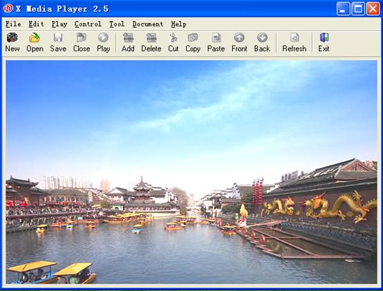
Multi-media programming player
DBSTAR multimedia programming player is the LED controller software ,which has formidable function ,easy to operate ,.May play MS Excel document, MS Word document, the sound document, the Flash document, the Windows media player, the specific text, simulates the clock, the video input, the digital clock, the picture document, the text document ,the DBSTAR software has combined the synchronous and the asynchronous controller card ,as well .allow kinds of display body settings. the software can adapt module insert .you can update or add new functions according to you requirements
Chapter one
software installation
System requirement
t HDsno less than
t Memorysno less than
t operating environmentsWindows95/98/NT/2000/XPt
Installation steps
tnew a new catalogue on the computer hard disk, Such as CsLEDtCopy the five documents (InstMsiA.exe InstMsiW.exe Setup.exe Setup.ini XMPlayer.exe)to the new foldertCsLEDttRun or double click tSetup.exett
2.the screen will pop the following messages 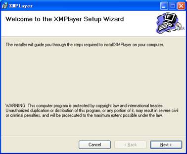
3.presstNextt it will pop the following dialogues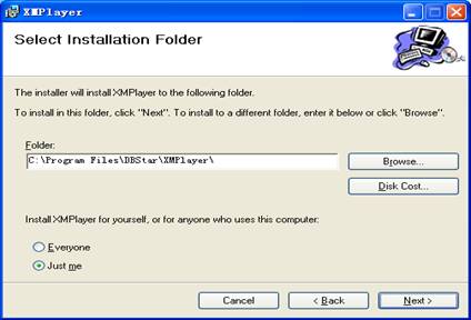
selecttEveryonetortJust met according to your need and then press tNextttThen go to next step to install.
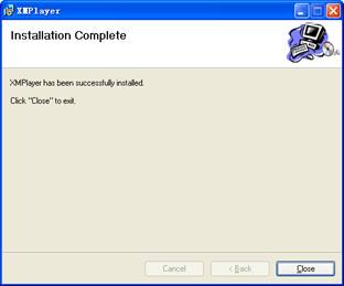
twhen pop the following dialogue ,the desktop will show coping document dialogue presstClosetto complete installt
Note:<1>.some
computers operation system may pop the following dialogue : 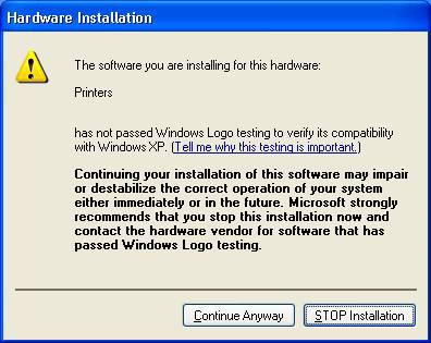
Please press  button to finish install.
<2>.some computers may have installed Anti-virus software, please set it ast allowingt
<3>.it may all English version when you install them
5.after finished install, the screen may produce  icon automatically
Interface introduction
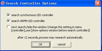
Double click ![]() icon ,the computer may find the main card automatically
,such as the following picture :
icon ,the computer may find the main card automatically
,such as the following picture :
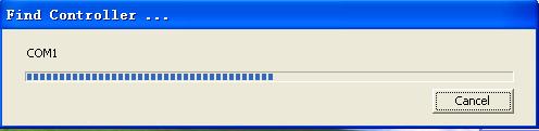
if the computer find one or more main card(one PC may control more DB2007 main card ) ,it may enter the operation system automatically such as the following picture :
Note if the computer have not connected Main card ,the software may work 30minutes ,and the main card control setting function may be closed .
chapter two
Menu bar and Tool bar
 Menu bar
t Document menus
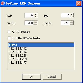
newsuses new a new playbill document.it may work when you finished build a new LED screen ,such as the following picture.
ttopt tleftt mean that the build LED screen may display at the top of your computert,twidtht and theightt mean that the width and height of you screen, the height ,may be the same as your screen
If you choose tARM
opensuses open edited playbill documentst
closesuses close currently playbill document
savesuses for save currently playbill document
Save assuses for save a new LED PLAYER document
Save all: the player may support many screens and many playbills at the same time
Issue: when the system connect so many Asyn controller cards ,it may send playbill to all systems, if the PC have not find Asyn controller cards ,it may not work
languagesuses for choose language ,such as English ,simple Chinese. what we designed are all module way of design, if you want to choose that you want language ,you can input it into the module. the three smile face icon are the language connection
Notessuch as :if
you choose Windows XP as operation system, if you choose Traditional Chinese,
the software on the menu and all the Chinese characters may come into a hash . find those phenomenon, please tick in the system 'control panel',
'Regional and Language Options' to the 'preferences' panel
'standards and formats,' selected as the 'Chinese (
exitsexit to LED play studio
notesplease save the doc which you editing when you exit, the software may not save present status when exit,just can open or build .
Edit menus
addsuses for add program to make up item.
deletesuses for delete currently program or follower contents.
cutsuses for cut currently program item and follower contents
copysuses for copy currently program item and follower contents
pastesuses for paste currently program item and follower contents
move frontsuses for move front currently program item and follower contents, click one time may exchange with the front same degree program one time .such as ;if you have selected some programs (not the first program )click tmove frontt the playbill may exchange the position with the front program ;if you have selected sub-window in the sub-playbills (not the first sub-windows)click tmove frontt the sub-window may exchange the position with the front sub-window; it may also suit to all items ;playbills ,LED screen ,program, sub-program, sub-windows.
Move backsuses for move back currently program item and follower contents, click one time may exchange one with the same degree items.
Hidden edited content: uses for hide the editing program
Display:the edited content may display in the top of the desktop
t Play menus
Playsplay the selected programt
Pausespause the playing programt
Stopsstop playing program.
Mutesmute playing programt
t Control Menus
Controller configurescan set parameter in the LED administrate
Remote controllersmay add remote facility IP address(main use in ARM9.0)t
Asyn sendingsWhen you select ARM9.0 special program,
the asynchronous sending may available, click may sending
parameter to ARM9.0
Open screensuses for sending parameter to open LED screen t
Screen stillnessswhen player playing ,the screen stillness
may change into can option item When click it the screen may
stillness, the same as pause function
testsclick may send parameter to the screen to testing
auto-adjustment:when the main card connect the brightness sensor, it can adjust LED bright
optionsclicktoptiont may set the player automatically starts, along with the computer ,when load playbills ,start change the position of mouse delete /exit ,you need confirm. When close playbill menu ,it may hint that save record play /system diary ,save diary t
t Tool Menus
Play PowerPoint documentsmay play edited PowerPoint Document beforehand
PowerPoint bitmapsmay change PowerPoint doc into bitmap format
Word bitmapsmay change Word doc into bitmap format, play
DVDVCD or CDsmay play already prepared DVDVCD or CD need
DVDVCD playert
New Word documentsmay new a new Word format t
Playbill menu:when editing many LED screens at the same time, it may display LED screen order so that easy to editing
t Help Menu
Aboutsdemonstrate software name and company information if the customer requirement ,may realize demonstrate customer company LOGO.
Tool bar
t software editing sate as follows:s
![]()
t software playing state as followss
![]()
The above Tool bar functions are the same as Menu bar
Chapter three
Playbill manufacture
Select screen type and program window type
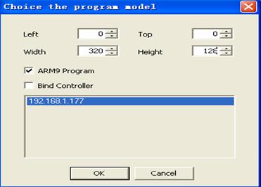
Adds file by right click it may pop the dialogue tchoice the screen modeltdialogue we can set just according to the screen, if your system aim at ARM9,you should choosetARM9 programt or nottAfter finished setting ,click tOKttFor example: we can choose width:320pixels,height:128 pixels
Notes
Left: mean the left of your computer display
Top: mean the top of your computer display
Height: mean player windows height
Width: player windows width
ARM9 program :when you choose ARM9 system ,you can click it ,the software may supply related ARM9 system interface and function
Bind controller: mean the size of main controller card have defaulted ,you can not change any more.
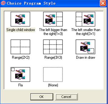
Then it may pop the dialogue tchoice program stylet it contains 7
kinds of display module for your choice .you can choose the style ,or design it
by yourself. 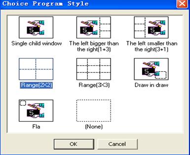
For example , we can choose range(2*2) style, and then click tOKt
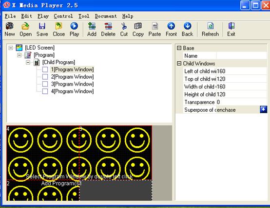
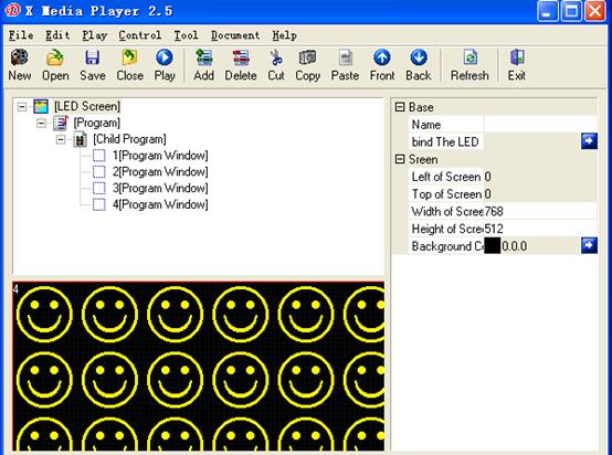
In the software interface we can see the program window model may have four child windows, right click each child windows may add program materials, or move dashed line to adjust the size of the child-windows. meanwhile we can see the left tprojectt may produce a playbill menu, and the first child window icon may display grey shading, in the right tpropertyt frame also produce correspondence child windows property. others may display red color .
You can default name so that easy to remember , otherwise , right click playbill may add LED screen .
LED screen introduce
Click [LED screen]
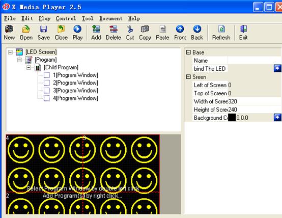
In the tpropertytcan define LED screen nametthe background color of the screen and so ontThe screen demonstration coordinates position as well as the width and do not have to modify highly generally. The control card binding establishment may cause each tLED screent through the control card binding, realized simultaneously controlled many display monitors functions
[program bill]introduction
Click item [program bill]s
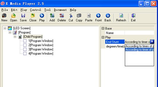
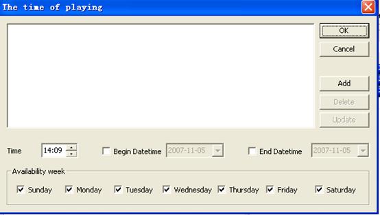
In the property fence can default program names, click blue arrowhead button, may choose way of play ,and way of finish and times setting /time The broadcast way has sequence broadcast, fixed time broadcasts, the overall situation broadcast, the manual broadcast and the emergency broadcast
Order plays according to its edition successively to playt
Schedule playschoice schedule play, schedule setting option may be available choose, Clicks on its right side blue color arrow button to jump out the following window, according to needs to establish the parameter, then the click to add the parameter which will establish , include the program time, click tOKt;
Global play: if you choose global play, the program may play all the time
Manual play: if the program set as manual play, it may play till you click it ,
times and timing value are the seconds respectively .ending way is base on play times and play timing
Insert play: in the process of playing ,you can choose the item if you want to insert other programs ,the play program may work when playing programs.
[Child-program] introduce
Click item [child-window] as the following picture
In tpropertytfence can default program names, click blue arrow may choose end way and set times /timing
[Child-window] introduce
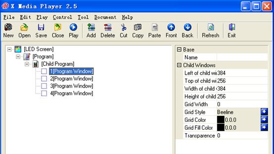
In the tpropertyt may set child window grid style, color and fill color ,such as sub-window demonstration coordinates position. The width and the height generally does not change .Sub-window transparency from 0 to 100 level of gradation strengthen gradually, may set according to the customer use
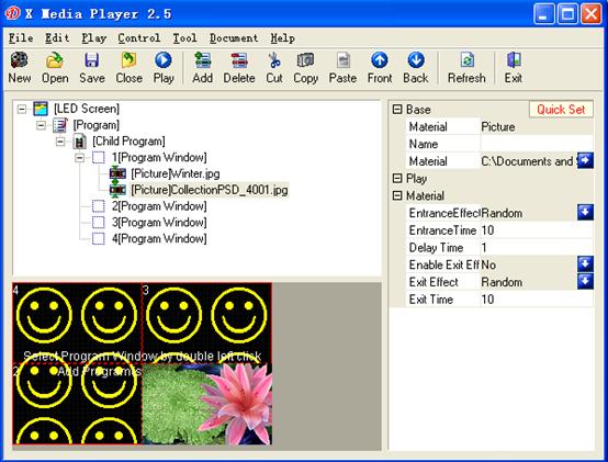
[Add program materials]
Click [child-window] to add program materials, or add program materials in the program windows or right click to add
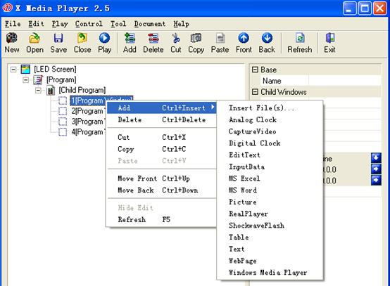
Each child-windows may contain many kinds form of materials, such as :insert file, flash, MSword file, MS Excel, Realplayer ,single line text ,digital clock and so on
Materials property introduce
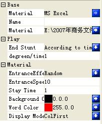
 <1>.MS Excel property
At present ,we have 53 kinds of stunts ,meanwhile we are developing others continuously ,the following table for your reference:
order |
stunt |
order |
stunt |
order |
stunt |
| |
random |
|
Scan1 corner3 vertical |
|
Mosaic 1 slender |
| |
static |
|
Scan1 corner4 vertical |
|
Radar CCW |
| |
Push up |
|
Close horizontal |
|
Dual Radar CCW |
| |
Push down |
|
Open horizontal |
|
Quad radar CCW |
| |
move left |
|
Close vertical |
|
Radar CW |
| |
Move right |
|
Open vertical |
|
Dual Radar CW |
| |
Move corner 1 |
|
Close corner1 |
|
Quad radar CW |
| |
Move corner 2 |
|
Close corner 2 |
|
Check board |
| |
Move corner 3 |
|
Open corner1 |
|
Random line |
| |
Move corner 4 |
|
Open corner 2 |
|
Quad to center |
| |
Scan up |
|
Across vertical |
|
center to quad |
| |
Scan down |
|
Across horizontal |
|
Quadto center(cross) |
| |
Scan left |
|
Blind vertical |
|
Centerto quad(cross) |
| |
Scan right |
|
Blind horizontal |
|
developing |
| |
Scan corner1 oblique |
|
Zoom corner |
|
|
| |
Scan corner2 oblique |
|
Zoom corner 1 |
|
|
| |
Scan corner3 oblique |
|
Zoom corner 2 |
|
|
| |
Scan corner4 oblique |
|
Zoom corner 3 |
|
|
| |
Scan1 corner1 vertical |
|
Zoom corner 4 |
|
|
| |
Scan1 corner2 vertical |
|
Mosaic |
|
|
Entrance time scomplete times which the stunts need from enters the stadium to enter the pause condition to the graphic display integritytValue range:0-10000 each number stands for 0.1per second.
Stop timesfrom the graphic display integrity to enters the stage time. The unit for reality second.
Display modelsthe overall zoom, display Excel graphic completely according to the size of the screen
Column firsttSif the graphic is big may display column completely first. such as the following pictures .picturet
Row firsttSif the graphic is big may display row completely first portrait demonstration integrity first, such as picturet
| |
|
| |
|
| |
|
| |
|
<2> MS
Word materials property
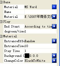
Entrance stuntstentrance timetstop time are the same as Excel material propertyt
Background colorsmay choose the font background color(pay attention to the
differences between font color and background color in generally the color of Word
font are black, at the same time ,the screen background are black too, which may
cause black screen )t
Color transfersMay choose the writing color invariably, the black whitening, black and white counter-, the counter-color
<3> Realplayer materials
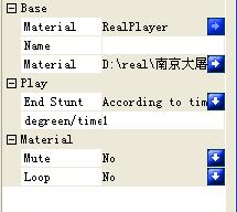
mutesmay set mute model for Realplayer document.
cyclesmay set cycle playing for realplayer if you choose cycle playing it may playing the doc ceaseless.
<4> Flash material property s
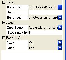
Cycle: may set cycle play flash
Automation: mean flash can play automatically
<5> windows media player material property
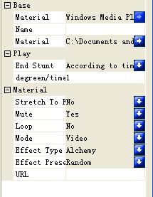
Cyclesmay set cycle playing for windows player if you choose cycle playing it may playing the doc ceaseless
3 kinds of display modelsvideo Visualization effect no displayt
7 kinds of Visualization affections imaginary, the atmosphere, the stripe and the wave, the group, particle, multi-angles of view, laser beam.
<6> single line text material property
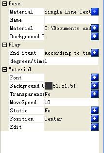
Background picturesclick the right blue arrowhead may add bitmap so as to the background, when add bitmap ,you should set ttransparence tto tNOt
Background colorsmay set the color for single text background pay attention to font color and background color
transparencessingle text can remove background color setting just display windows content
move speedsthe time which a picture element needs. the bigger values walks, the slower the speed
staticswhen the character static displayt
positionsthe position of single text.
topsthe single text located in the top of child window.
center: the single text located in the middle of child window.
bottomsthe single text located in the bottom of child window.
<7>Analog Clock material property

When you choose simulate clock format materials ,it may display a clock in the screen window, you can adjust and set parameter by yourself
Clock captionsmay input area or users needed character ,display in clock desktop.
Caption fontsset the clock caption font.
Clock face stylessquare rectangle round ellipsetDefault as roundt
Hour mark colorshour mark color in the clock face, default as white
Hour mark styleshour mark style in the clock face, may have square, round, default as round
Hour mark sizeshour mark size in the clock face, value range 0tS30000 default 3 pay attention that the size too big may display abnormal
Minute mark colorsminute mark color in the clock facetDefault white
Minute mark stylesminute mark style in the clock face square and round default round.
Minute mark sizesminute mark size in the clock face value range0tS30000 default 3 pay attention that the size too big may display abnormal
Hour hand colorsmay choose the color of hour hand, default red.
Minute hand colorsmay choose the color of minute hand, default red
Second hand colorsmay choose second hand color, default Red
Data fontsmay choose data font in the clock face.
Data formatsmay revise data format y4. m2. d2
Month two day twotWhen revise ,may choose even.
Week fontsmay choose week font in the clock face.
Week formatsMay revise week format.
transparencesclock may delete background display.
Background colorsmay set the background color, default grey.
Second adjustment secondsmay revise second according to local time
Minute adjustment minutesmay revise minute according to local time
Hour adjustment hoursmay revise hour according to local time
Day adjustment daysmay revise data according to local time
<8> digital clock materials property
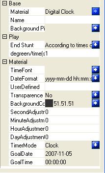
Time modesclocktStSdisplay system offered timet
Count downtStSset global data and time, demonstrated the current time and the goal time differencet
TimertStSDemonstration the time starting to play the format:
Global Datasthe global data of count down
Global Timesthe global time of count down.
Other property parameter please read (8) simulate clock.
<9> picture materials property
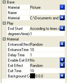
Property parameter you can read (1) MS Excel material property
<10>.text materials property
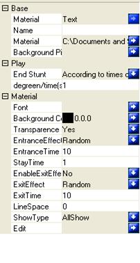
Entrance time: mean entrance program according to setting time
Line Spacesthe space between line and line, value range:0tS30000t
Show zonesmay choose all show line show or char show
Edition: may edit according to your own requirements
Other properties please read(2) MS Word material property and single text material property.
examples
for example: we may play a multimedia player program ,choice tinsert
filet in the child-program , it may pop a dialogue topent to look for your computer goal documents, otherwise
click the blue button in the tpropertyt ,you may find or revise goaled
document, Or right click project [child window] ![]() icon click tchoice
material t may also reach
the goal of adding document.
icon click tchoice
material t may also reach
the goal of adding document.
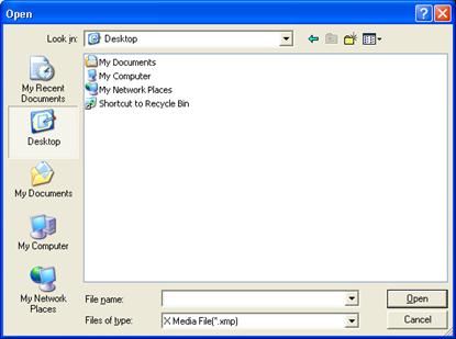
Choose what you want to play, and then open it ,may pop multimedia player dialogue,
You can default program name by yourself in the tpropertyt. you also can adjust by your own needs, mute ,cycle display model, visualization stunt ,long distance URL setting
Especially declaration s
When you choose tmutet or tcyclet as tOKt. you should set tadjustmentt as tOKt at the same time .
Add program to each child windows in turn. click move front in the menutedittmay exchange the selected child window program content with the front child window and program content at the same way move back mean that exchange the child window with next child window.
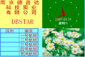
After finished , click tplayt in the tool bar. or press shift F9,It may display the document in the desktop coordinates position. different child window content may display Simultaneously in one screen ,if you set different child windows in the same position ,the current child window may cover the front child window content. the content in the grid is the same as the content in the LED screen .
The software support multi play windows player , editing at the same time, may never affect others.
Enclosure introduction
One program may contain so many LED screens ,each screen may have one or two main controller card, but it can realize play simultaneously .one LED screen may contain so many programs ,the program can set play style ,the program may be played according to related setting, default way of play as play in turn ,one set of program may have so many child programs. the child program may play according to the order of edition. the child program may also play according to sequence playing.
PART two
DBT-Q2007full color synchronous controller system installation
Chapter one . hardware cognition
System requirement
һtinner controller installations
t Host computers1 vacancy PCI slot
1 usable USB connection
t HDsno less than
t Memorysno less than
t software environmentsWindows95/98/NT/2000/XPt
ttoutside controller installations
t Host computers1 usable USB connection
t HDsno less than
t Memorysno less than
t software environmentsWindows95/98/NT/2000/XPt
remarksoutside controller may be controlled by the DVI output Notebook computer
main controller card introduction
07 Main controller sending card s
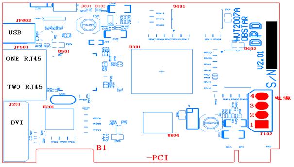
Picture introduces
B1---PCI slot Uses for inserting the computer PCI slot, our main card contain three way of connections: PCI connection, USB connection,RS232 connection. generally speaking , our outside controller adopt USB communication connection
J201----DVI connectionsDVI connection ,connected the computer display card DVI connection with the necessary DVI line ,There are four lights nearing to RJ45 output connector(2 green,2 yellow),only one yellow light blink when connect with display card ,you should open the second output of the video card.2 green light bright and 1 yellow light which is in the middle of the RJ45 is slow blink, but one of yellow light in the side of RJ45 may blink quickly .how to open video card second output you can read Part 3. chapter 1 video card setting
J501---Two RJ45 data outputs: main controller card signals outputs. nearing to the
USB connection is the first output. and then the second output, connecting HUB card
input port by a standard cat 5e cable .one transfer output can driver 640 lines
data (detail about how many lines drive may according to your screen)
RJ45 and DVI graphic introduce
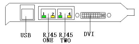
Baffle introduce
NO1.green light: long time bright ,the main card work ,the first RJ45 have the signal output, or not
NO2.yellow light: twinkle mean that FPGA process work fine
NO3.green light: long time bright ,the main card work ,the first RJ45 have the signal output, or not
NO4.yellow light: twinkle ,mean DVI output to main card work fine ,if the video card output have not opened ,or main card work abnormal, the light may not bright
Standard USB connection :connecting computer USB connection by necessary USB line after connected D601green light will be bright, it means that USB connection work fine or not,when main card slot in PC ,it have through PCI communication, the main card still can work without USB line.
JP602---- USB-B slot ,it uses for computer communicate with main card, when use USB-B ,the main card can work without USB line.
D601----green indicator light,after connect the USB line with the PC ,the D601 light may bright ,or not
D102----red indicator light,it it may bright when main card slot in PC or power J102 .if not ,please check the reason carefully !attention :before you have not found reasons ,please not going on the next step in case break the main card.
J102----power input mouth ,NO1 and NO3 should connect +5V,NO2 and NO4 connect GND. when main can slot in PC ,may not power on, because it have power through PCI
HUB board (receiving card ) introduce
DBT-Q2007 HUB(receiving card)
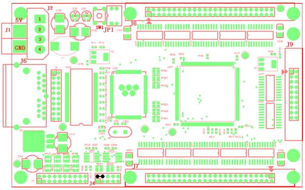
J1---Power connection ,5V---+5V,GND
J2tSPower slot,NO1 connect +5V,NO2,NO3 connect GND
J4- procedure input mouth, finished input procedure ,NO2,NO4 feet must be short circuit ,such as the picture.
J6----two RJ45 signal , connecting HUB card output port by a standard cat 5e cable
J7,J8,J9----data output mouth,J7,J8 is the 50PIN cable line jack, connecting kinds of screen in the market by a 50pin flat cable line, each 50pin cable line can output 8 data line,J9 is our company professional design ,which used for add more 8 data line ,(24 data signal output ,may connect different screens by our different switch boards),J8 is the first output mouth ,when connect it ,please make sure GND to GND ,there is double arrow mark is the first PIN feet.
JP1---OE switch ,ON is work normal
SW1----display self-testing button, under the condition of no main card ,you can press the button ,it may realize self-testing(RGB),once you connect net line ,it may end self-testing.
Switch board introduce
2007 standard switch board (DBSTAR-HUB-37)
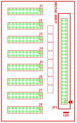
JP1---50pin flat cable line, connecting HUB with switch board by 50pin COM, Attention: the arrow mark is the first pin feet, which is correspondence with HUB 50PIN
J1-J8--- there are eight 20pin COMs, connecting LED screen data input ,when connect please pay attention to GND to GND
LED----is red indicator light, the switch board need not connect power line, attention: make sure right connect.
t24PIN data output switch board
Switch board(DBSTAR-HUB-37(24PIN)
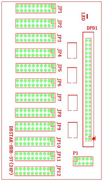
DPD1 50pin flat cable line, connecting HUB with switch board by 50pin COM, Attention: the arrow mark is the first pin feet, which is correspondence with HUB 50PIN
JP1-JP12--- there are twenty 20pin COM, connecting LED screen data input ,when connect please pay attention to GND to GND
LED----is red indicator light, the switch board need not connect power line, Attentions make sure right connect.
P1---10pin flat connector plugs, you can divide HUB board JP9(20PIN flat cable line)into two parts from middle, one of 20pin flat cable connect JP9,another head using two 10pin flat cable line connect 24pin switch board JP1 respectively
The first 10pin NO1 feet to 20pin NO1,the second 10pin NO1 to 20pin NO11
The 24pin mean that the switch board have 24 data lines output.
Outside controller introduce
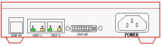
NO1.green light: long time bright ,the main card work ,the first RJ45 have the signal output, or not
NO2.yellow light: blink mean that FPGA process work fine
NO3.green light: long time bright ,the main card work ,the first RJ45 have the signal output, or not
NO4.yellow light: blink ,mean DVI output to main card work fine ,if the video card output have not opened ,or main card work abnormal, the light may not bright
Standard USB connection :connecting computer USB connection by necessary USB line after connected D601green light will be bright, it means that USB connection work fine or not, when main card slot in PC ,it have through PCI communication, the main card still can work without USB line.
DVI connection: connect with video card DVI ,when the video card second output open,NO1.NO3 green light,NO4 yellow light may bright at the same time ,NO2 and NO4 yellow light may twinkle continually
Power: 220V
Chapter two
hardware installation
hardware installation steps
t Turn down the Power Supply of computer and open computer box
t install DVI connection(inserting correspondence slot)and fasten it with screws
t select a vacancy PCI slot, loosen the screw and take the baffle down , and then insert the DB2007main controller in the PCI slot, fasten it with screw, when main controller card insert the PC ,the +5V Power Supply jack(J102)in the card need not connect Power Supply .
t connect the display card DVI and full color controller card DVI by DVI transmission line.
tconnecting true color control cardts any one of data transmission
RJ45ports and HUB scan board RJ45 by a standard cat 5e cable ,the longest network
line from control card to HUB is
tConnecting main control cardt USB port and PCts USB port by USB line. because some computers USB port have not output, so please insert it directly in the host board output of the computer ,moreover ,because of computer or operate system ,you need insert USB line after finished installing driver. please follow introduction .
tConnecting HUB scan board data output network port (J8 the first output port)and switch boards data input port, pay attention to interface definition correspondence
Connecting switch board data output port and LED display data input port by Correspond flat cable .and according to display data output port definition(may make switch board according to different connection definition ).
put out network line, power on LED screen ,if it has bright dot or bright line,mean the card connection abnormal ;if black screen mean OK.
Confirm the connection correction ,Power on .and go to next step you can read
Part 3 chapter .1 video card setting (when use DVI connection)after finished setting
You can enter LED player
Chapter three
parameter adjustment guide
open interface
double click software icon open tLED player programt then click menu tcontrolt item and then click tmain controller settingt it may pop the following picture:
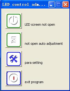
You can click tparameter sett and then input password
the password: DBSTARLED
Attention: our company led player program software password is:DBSTARLED, before you enter the setting interface ,please make sure you are familiar with your screen ,or it may make your screen display abnormal
The sending interface as the following picture :
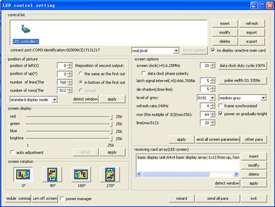
tLED control software setting introduce
Zone 1: control list
Sending card demonstration : display LED controller card
Insert: add new item ,special for adding ARM9
modify: when you use ARM9 ,the item may modify ,it uses for modify IP address
delete: delete main card and related parameter
refresh: refresh control list
import/export: import set parameter for using next time
connect port: way of connection (PCI,COM)
Identification: sending card version
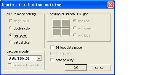
type:main card work status (real pixel, virtual pixel double color and so on)you can choose just according to your screen
Try to connect : try to connect main card, when you use ARM9 it can work
No display unactive main card: may not display the unactive main card in the control list
Zone 2.position of picture output
position of left(X)position of top(Y): Picture display in the PCts position
number of column /row : the range of one main card can driver.
video card output refresh: 1024*768
the position of second output: when you choose tsame as the first outputt mean the picture displayed from two network mouths in the main card may same .when you select tunder the first outputt mean displayed picture content from tthe second outputt is the tthe first outputt shows that the content of the image below.
detect window: show the position of image in the computer
sending : send parameter to main card
screen display
Brightness: adjust RGB ,generally speaking, we can set more bright in the day
auto-adjustment: set brightness when you use brightness sensor
setup: it may work when you open auto-adjustment, adjust brightness and COM
screen rotation
there are four screen rotations :0,90,180,270.it may apply to special strip screens
schedule command: you can set time according to your need
close screen: close LED screen
power manager: power switch manage
Zone 3 Screen options
In the area ,such as data clock frequency ,data clock duty cycle ,latch signal pulse width and de-shadow time are all default value .you can not revise .
de-shadow time :when your screen appear dark bright ,you can improve de-shadow time .if still have the problem ,please check OE ,meanwhile adjust de-shadow time may apply to scan screen
level of grey: generally speaking ,the best affection for double color screen is:256 ,indoor full color screen:4096 level. outdoor full color screen :16384 level
the higher the level of grey ,the better the picture
sending :send the parameter in the screen options to the screen
send all: send all parameter to the screen
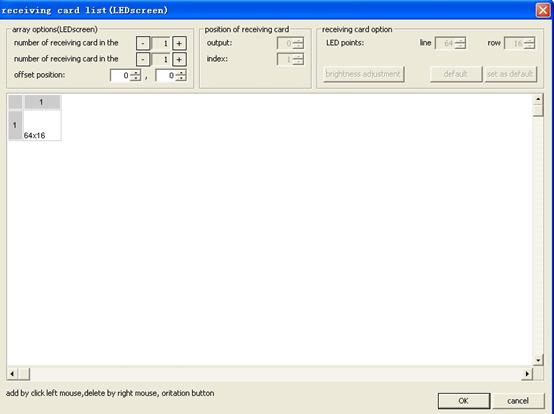
Zone 4 Receiving card array (LED screen)
add: add one group of receiving card array (scan HUB )
modify: revise scan board (HUB) array and some parameters
delete: delete one group of receiving card array
sending : send the parameters which have set
sketch window: show the position
enclosure parameters:
wizard: help
send all: send all parameters to the LED screen
exit: exit to the manager process
examples
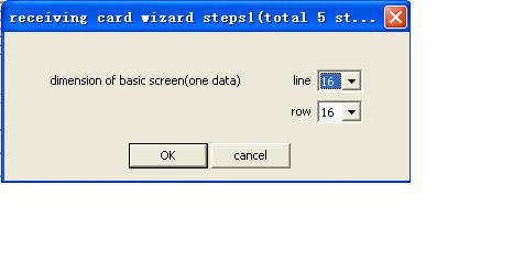
Now we are set an static screen 4lie4zhe 128*128 full color screen as an example.
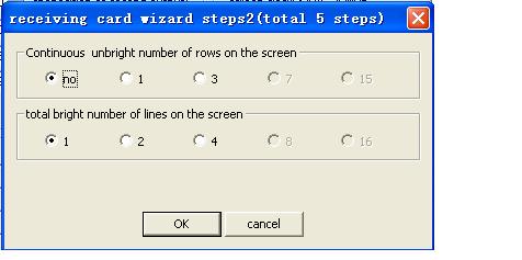
First you open software and then click wizard , Then you can go to next step set the parameter such as: level of grey, de-shadow time .when you have adjusted ,please send parameter again !
at
last click the ![]() button may save the
entire receiver card parameter .when you use it next time just click
button may save the
entire receiver card parameter .when you use it next time just click ![]() button
may pop the saved doc in your PC. then click tsendingt
button
may pop the saved doc in your PC. then click tsendingt
as the following picture
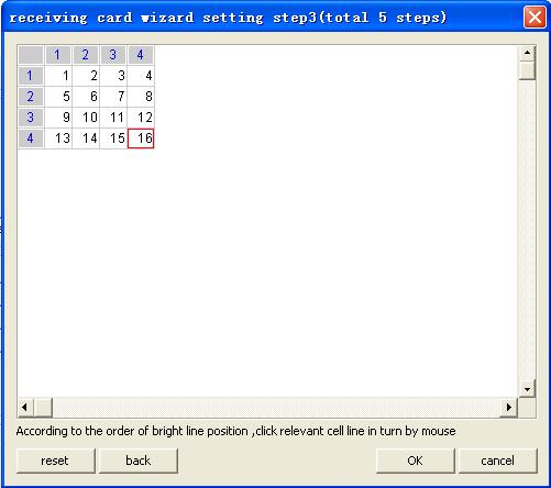
Click correspondent color cell by mouse according to display color, then click tOKts
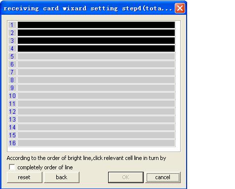
Click correspondent cell, brightness lines according to the order of brightness lines. then tOKtt
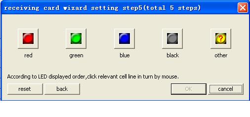
Click correspondent color cell by mouse according to display color, then click tOKts
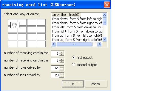
when go to this step ,the screen may be bright ,but the content displayed in the screen may the same in the different screen modules. if you want to show what you want to ,you need go the receiving card list to set the array, such as the following picture:
click ![]() icon ,may easy to check the position
of coordination .right click may
check the level of grey or scan lines, after test then exit .
icon ,may easy to check the position
of coordination .right click may
check the level of grey or scan lines, after test then exit .
Part three accessory
Chapter one .video card setting
ATI vedio card setting
Click the desktop ,choose the tpropertiest to click, and choose tsettingt option ,then click the tadvancedt button, click the tdisplayt button, set tFDPt button to be green, then click tapplyt

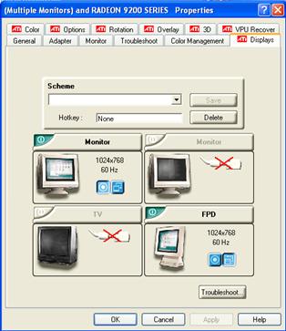
Especially declarationssometime you need adjust you computer resolution high, for example:1280*1024,at the time you need make sure the FPD display resolution, if it is 1024*768 as well mean that the display just support 1024*768 resolution only.
Choose the tmonitort option ,set the monitor refresh:60HZ.t
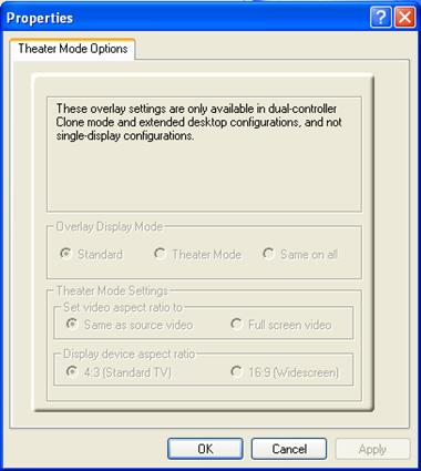
if you want to play video, click toverlayt button, then click tClone mode options..t button, choose tsame on allt and then click tApplytt
![]()
NVIDIA display card setting
Right click on the desktop, may pop setting menu, as following picture:
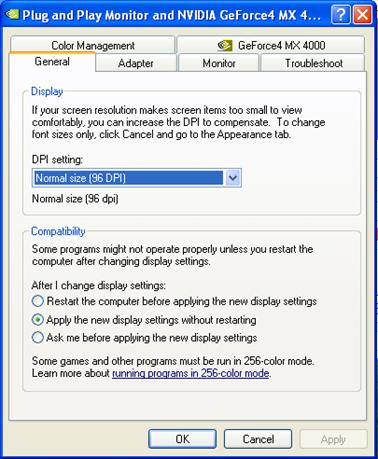
Click tpropertyt, may pop the following dialogues
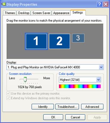
Click tsettingt and then click tadvancet button, as the following picture
Click tGeForce4ttmay pop the menu and then click nView, as following picture s
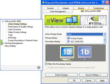
In the nView model ,choose copy and then click tapplyttIf you want to play video, please click thelptin the advance,or tfunctiont .
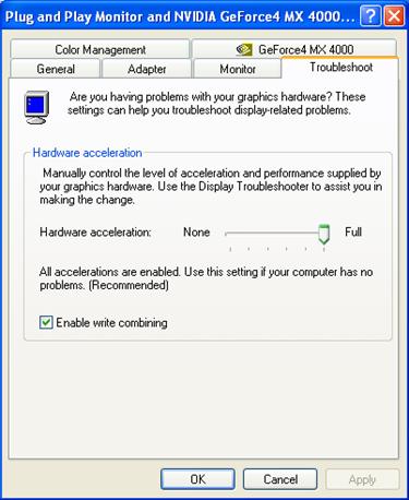
Set the hardware accelerate to be base accelerate or NO hardware accelerate, then click tApplyt.
ATI driver program installation and problem resolution
ATI public version driver may test
the manufacturer ID when you install them ,if INFdoc not contain ID number,it
may hit that tcan not find or unavailabletinformation .which may not install
driver
how to install orign ATI display card driver under NIVAD display ?
Please operate following the stepss
(such as radeon7500s+XP
OS+wxp_radeon_6_13_10_6015.exe tDownload
driver program wxp_radeon_6_13_10_6015.exe tzip to some
cataloguetD:wxp_radeon_6_13_10_6015 tlook for ATIDRIVE
child catalogue D:wxp_radeon_6_13_10_6015R6xpAtidrive t list all info doc under child ATIDRIVE generally speakings xp inf docs atiixpxx.inf
win9x inf docs atii9xxx.inf
w2k inf docs atii2kxx.inf
(xp doc mean atiixpag. inf)
5tin the atiixpag.inf
doc look for ati.mfg or mfg
you can find radeon7000,radeon7200,radoen7500,radoen8500
and so
6tfind 'RADEON
7500' = ati2mtag_RV200,
PCIVEN_1002&DEV_5157&SUBSYS_
delete'&SUBSYS_
Chapter two. Network line manufacture
Direct line manufacture
t Removing the
|
Picture 1 |
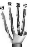
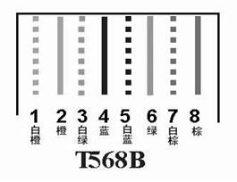
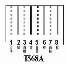
t Connecting the wires, the connection standard is EIA/TIA T568B.1.2 is a pair of twisted wires:3,6 is a pair of twisted wires;4,5 is a pair of twisted wires ;7,8is a pair of twisted wires ;either the end of the line is connected according to the standard T568B.the pairs of wires are arranged
According to the colors (as the figure2;white-orange;2orange;3,white-green ;4, blue ;5,white-blue;6,green 7, white-brown;8, brown)
t Note The green wire should be placed across the blue pairs, it is easy to make mistake that putting the white Cgreen and the green wire together ,that will arise the disturbing and lessen the transmission efficient.t
picture 2
tafter connecting the wires well,
keeping the twisted-pair in order ,and then cutting the bare twisted Cpair down
with special purpose pliers. remaining approximately the
|
Picture three |
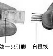
tafter ensuring the correction of the connection ,to jointtheRJ45 port by the RJ45 pressing pliers, such as the following picture .
|
Picture four |
tthe connection of the other end of RJ45 port pin is as the same as the above-man tioned method .both the end of RJ45 port connection must be completely consistent ,finally ,using the tester to test,
NOTEsDirect line may used in DBT-Q2007 controller system.
Reciprocity line (intersect line)
t intersect
line manufacture and standard net line manufacture are the same. the only
difference lies in the both sides color
streak.standard direct line both side use T568B while reciprocity line one side use T568D
another side use T
T
tttt
Green white green orangewhite blue blue and white orange brown and white brown
T568B order
tttt
Orange and white orange green and white blue blue and white green brown and white brown
Direct line and coordinate line use situation
tLED controller connect computer
Twisted-pair is intersect line connection.
tLED controller connect local net
Twisted-pair is direct line connection.
Chapter three
DB2007system testing procedure
Step 1sfinish the hardware installation accord with chapter two introduction ,the main controller card (D601) light may bright ,it mean that USB line connect fine .
Step 2spower on, the LED1 (red light indicator) in the switchboard may bright ,if not ,it indicate that the flat cable line may not connect fine ,the LED1(green indicator) in the HUB board may blink,LED2(red indicator) may bright, if not ,it maybe the power connection problem .The D102(red indicator) on the main card may bright, the green indicator in the output port may blink, the yellow indicator may bright ,if the yellow indicator not bright ,may check whether the DVI line OK, and then operate accord with chapter three display setting till the yellow indicator bright ;meanwhile it may other possibility reasons such as :The power connect counter, the power have not output, less than or more than 5V .
Step 3schecking the networkline manufacture, connection whether sturdily, or length whether too longt
Step 4 schecking the display screen is bright or not ,if not back to step 3,and check switch board definition is matched with the LED screen interface ,the connection is corresponded one by one ,turn on the power and test it again .
|
Politica de confidentialitate | Termeni si conditii de utilizare |

Vizualizari: 3929
Importanta: ![]()
Termeni si conditii de utilizare | Contact
© SCRIGROUP 2025 . All rights reserved