| CATEGORII DOCUMENTE |
| Bulgara | Ceha slovaca | Croata | Engleza | Estona | Finlandeza | Franceza |
| Germana | Italiana | Letona | Lituaniana | Maghiara | Olandeza | Poloneza |
| Sarba | Slovena | Spaniola | Suedeza | Turca | Ucraineana |
OCIMF
Single Point Mooring
Maintenance and Operations
Guide
The OCIMF mission is to be recognised internationally as the foremost authority
on the safe and environmentally responsible operation of oil tankers and terminals.
Oil Companies International Marine Forum
Table of Contents
Section Page
LIST OF ABBREVIATIONS VII
INTRODUCTION 1
CLASSIFICATION SOCIETY RULES AND OTHER PUBLICATIONS 3
Rules 3
Publications 3
2.2.1 OCIMF 3
2.2.2 International Chamber of Shipping (ICS) 5
2.2.3 ICS/OCIMF/IAPH 5
2.2.4 International Maritime Organization (IMO) 5
SINGLE POINT MOORINGS
3.1 Types of SPMs 7
3.2 CALM 7
3.3 SALM 8
OPERATIONAL PROCEDURES
Preparations for Berthing 13
4.1.1 SPM Pre‑Berthing Inspection 13
4.1.2 Ship Board Measures 14
Mooring 15
Hose Handling 16
4.3.1 Hose Connection 17
4.3.2 Hose Disconnection 18
Cargo Operations 18
Ballast Operations 19
Unmooring 19
4.6.1 Assisted Unmooring 19
4.6.2 Unassisted Unmooring 20
Safety 20
Pollution 21
INSPECTION SCHEDULES AND PROCEDURES
Inspection Schedules 29
Pre‑Berthing 29
Weekly 30
Monthly 31
Half Yearly 32
Yearly 32
Inspection Procedures for CALM Systems 33
5.2.1 Surface Fluid Swivel 33
5.2.2 Surface Piping and Expansion Joints 33
5.2.3 Main Turntable Bearing 33
5.2.4 Anchor Chains and Anchors or Anchor Piles 34
Inspection Procedures for SALM Systems 35
5.3.1 Submarine
5.3.2 Anchor Leg 35
MAINTENAN CE AND MAJOR OVERHAUL
Planning 37
6.1.1 Factors Influencing Planning 37
6.1.2 Safety Precautions 38
Information Applicable to all Systems 38
6.2.1 Replacement of SPM Hoses 38
6.2.2 Replacement of Mooring Hawser and
Pick‑Up Rope Assemblies 38
Replacement of Chafing Chains 39
6.3. Information Particular to CALM Systems 40
Replacement of Main Turntable Bearing 40
Surface Fluid Swivel 40
Turntable and Ancillary Equipment 41
Anchor Chains 41
Buoy 42
Buoy Towage 42
PLEM 42
Information Particular to SALM Systems 43
Buoy Body and Anchor Leg 43
Submarine Main Swivel and Hose Arm Assembly 43
Base 44
PLEM 44
DIVING AND ROV SERVICES
Fundamental Principles 55
Minimise the Need for Underwater Intervention 55
Minimise Exposure to Hyperbaric Pressure 55
Contract all Underwater Work as a Service 55
Selection of Contractors 56
Inspection and Audit 56
Controls 56
Environmental Safety Considerations
56
7.2.1
7.2.2 Surface Visibility 56
Operational Safety Ckinsiderations 56
7.3.1 Over‑side Loads and Working 56
7.3.2 Surface Vessel Movements 56
7.3.3 Diving on Internally Pressurised Pipelines 57
7.3.4 Fishing from SPMs 57
Manned Diving Safety Considerations 57
Pressure Related Illnesses 57
Provisions for Treatment of Pressure Related Illnesses 57
Diver Entering and Leaving the Water 57
Head Protection 57
Use of Closed‑Circuit Television (CCTV) 57
High Pressure Water Jetting Equipment 57
Use of Hyperbaric Diving Services 58
Surface Oriented Diving 58
Self Contained Underwater Breathing Apparatus (SCUBA) 58
Surface Supplied Breathing Apparatus (SSBA) 58
Light‑Weight SSBA 58
Use of Nitrogen/Oxygen (Nitrox) Breathing Gas 59
Diving Team Size 59
Diver Competency 59
Use of Remotely Operated Vehicles (ROV) 59
ROV Capabilities 59
Types of ROV
60
7.6.2.1 Low Cost ROV (LCROV) 60
7.6.2.2 Observation Vehicles 60
7.6.2.3 Work Class Vehicles 60
SUPPORT FACILITIES 63
Craft for Marine Operations 63
8.1.1 Mooring Launches 63
8.1.2 Maintenance Vessels 64
8.1.3 Use of Tugs in Operational Support 65
Shore Maintenance Facilities 65
8.2.1 Yard and Storage Facilities 65
8.2.2 Facilities for Major Overhaul 66
8.2.3 Dock Space for Service Vessels_ 66
SPARE PARTS 67
9.1 Spare Parts ApplJ1cable to all Systems 67
9.2 Spare‑P 'rt Applicable to CALM Systems only 68
9.3 Spare Parts Applicable to SALM Systems only 68
RECORDS 69
Record Content 69
Typical Areas to be C(3vered‑ by the Record System 69
10.2.1 Pre and Post Mooring Checks 69
10.2.2 Operating Mooring Data 70
10.2.3 Equipment Performance 70
10.2.4 Overall SPM Performance 71
List of Abbreviations
API American Petroleum Institute
CALM Catenary Anchor Leg Mooring
CCTV Closed Circuit Television
CONCAWE The Oil Companies' European Organization for Environment, Health and Safety.
D Diver
DDC Deck Decompression Chamber
DIA Diameter
DIR Direction
HP Horse Power
HT Height
1APH International Association of Ports and Harbors
ICS International Chamber of Shipping
IM0 International Maritime Organization
m Metre
mm Millimetre
MSL
OCIMF Oil Companies International Marine Forum
Per Period
PLEM Pipe Line End Manifold
psi Pounds per square inch
Psig Pounds per square inch gauge
SALM Single Anchor Leg Mooring
SCUBA Self‑Contained Underwater Breathing Apparatus
SPM Single Point Mooring
SSBA Surface Supplied Breathing Apparatus
SWL Safe Working Load
Vel Velocity
VHF Very High Frequency
Section 1.0
Introduction
The efficient, safe and reliable operation of Single Point Mooring (SPM) terminals is largely achieved by the use of established operating procedures and by regular inspection and maintenance. Manuals providing detailed instructions to operation and maintenance personnel enable sound procedures to be established.
The basic objective of this publication is to provide guidelines to operators of SPM terminals to assist in the preparation of manuals for their particular terminal facility. This publication provides a framework and a basic outline of procedures based on extensive experience gained by several companies with various types of SPM facility. These basic guidelines should be supplemented and modified to suit the particular requirements of the SPM facility. A list of applicable rules and publications for reference purposes is provided in Section 2.0
The scope of these guidelines is restricted to the two most common types of SPM. These are the CALM (Catenary Anchor Leg Mooring) and the SALM (Single Anchor Leg Mooring). A brief description of both types of facility is given in Section 3. 0. SPM facilities specially designed to accept dedicated tankers are beyond the scope of this publication. Many of the guidelines, however, can be selectively applied to these and other types of SPM.
Section 3.0 should be supplemented by a description of the terminal organisation and by a detailed description of the particular terminal facility including charts, diagrams and local environmental conditions.
Outline operational procedures, inspection schedules and procedures, and guidelines for maintenance procedures are provided in Sections 4.0, 5.0 and 6.0 respectively.
Diving is inherent to the operation and maintenance of SPM facilities. Section 7.0 provides guidelines for air‑diving in the vicinity of SPM facilities to a maximum depth of 50 metres. Techniques for diving deeper than 50 metres are beyond the scope of this publication.
A general overview of the types of support craft and shore facilities required is provided in Section 8.0.
The safe and efficient operation of an SPM facility requires spare parts to be readily available in the event that replacement of components is required. Section 9.0 provides general guidelines for the quantity of spare parts to be held in stock. These guidelines are based on experience.
A comprehensive record system provides the most reliable basis for the establishment of rational inspection and maintenance schedules for a particular SPM facility. Guidelines for the type of records required are provided in Section 10. 0.
Section 2. 0
Classification Society Rules and
Other Publications
2.1 RULES
It is possible to classify SPMs in accordance with the rules and regulations of classification societies. Of the several societies that classify SPMs, the following have published rules:
American Bureau of Shipping
Rules for Building and Classing Single Point Moorjngs.
Det Norske Veritas
Rules for the Design Construction and‑ Inspection of Offshore Loading Systems.
Lloyds Register of Shipping
Guidance Notes for Single Point Moorings, Buoys and Similar Tethered Floating
Structures.
2.2 PUBLICATIONS
OCIMF
The latest editions of the following publications are applicable to the operation and maintenance of SPM facilities.
Guide to Purchasing, Manufacturing and Testing of Loading and Discharge Hoses for Offshore Moorings.
This publication gives the minimum specification of acceptable technical requirements to ensure the satisfactory performance of rubber, reinforced, smooth bore, oil suction and discharge hoses for offshore moorings. The specification is divided into two parts: technical requirements for commercial hoses and technical requirements for prototype hose approval. Notes to the purchaser are included listing items which should be specified or agreed with the manufacturer. It includes reference to double‑carcass hoses, lifting lug requirements, float design requirements, standardisation of bead float collars and standards for packing.
Guidelines for the Handling, Storage, Inspection and Testing of Hoses In The Field.
Gives guidance on the handling, storage, inspection and testing of hoses under service conditions.
SPM Hose Ancillary Equipment Guide.
Gives guidance on common descriptive terminology and technical requirements for the designer and operator of SPM systems.
SPM Hose System Design Commentary.
A commentary on the two most common types of SPM (CALM & SALM) reflecting modern practices, providing descriptive terminology together with an outline of present practice in the design of hose systems.
Recommendations for Oil Tanker Manifolds and Associated Equipment.
Gives recommendations aimed at introducing conformity in manifold arrangements for all ocean going tankers engaged in the transport of crude oil and bulk liquid petroleum products, including guidance on vapour recovery manifolds.
Recommendations for Equipment Employed in the Mooring of Ships at Single Point Moorings.
Gives recommendations aimed at facilitating correct matching between the SPM and the ship. Recommends that mooring equipment available at terminals be brought into line with these standards and that ships be provided with bow stoppers and associated fittings designed to secure and accept standard chafe chains.
Hawser Test Report.
Gives a complete description of the first major large rope testing programme. This was undertaken to determine the actual new and used strengths and rate of strength reduction of large synthetic ropes similar to those used as SPM hawsers. All the test data and analyses are included together with conclusi6ins and recommendations. It will be of interest to designers and operators of SPMs and to all who manufacture or use large, synthetic ropes for lifting and mooring.
Hawser Guidelines.
These three booklets are produced with the intention that rope manufacturers establish complete and detailed documentation of their synthetic fibre products, particularly those primarily intended for use at single point moorings.
Volume 1 ‑ Guide to Purchasing Hawsers.
Volume 2 ‑ Procedures for Quality Control and Inspection During the Production of Hawsers.
Volume 3 ‑ Prototype Rope Testing.
Marine Terminal Survey Guidelines.
This guide and the checklists appended have been published to provide a tool that may be used by terminal operators/owners to encourage the assessment of standards of safety and oil spill control at oil terminals on a world‑wide basis.
Oil Spill Contingency Planning ‑ A Brief Guide.
This guide aims to provide a general overview of the whole subject of clean‑up, in brief and simple terms, for the guidance of those in the oil industry concerned in contingency planning, government relations and public affairs.
Response to Marine Oil Spills (ITOPF).
This book is designed to be of maximum practical benefit to those involved in training programmes, contingency planning or actually responding to oil spills.
2.2.2 International Chamber of Shipping (ICS).
Ship/Shore Safety Check List Guidelines.
The check list covers the handling of dangerous liquid substances in bulk, including liquefied gases, and aims to ensure that there is a proper exchange of information between those responsible for the operations on board ship and those ashore.
Guide to Helicopter/Ship Operations.
This guide has been prepared primarily for the use of masters, officers and crew, but it also provides guidance for helicopter pilots with a view to introducing standardised operational procedures for helicopter/ship operations on a world wide basis.
OCIMF / ICS / IAPH
International Safety Guide for Oil Tankers and Terminals (ISGOTT).
This safety guide makes recommendations for practices to be adopted by tanker and terminal personnel to ensure safety in operations relating to the carriage by sea and the handling on tankers and at terminals of crude oil and petroleum products.
International Maritime Organization (IMO)
Recommendations of Safe Transport, Handling and Storage of Dangerous Substances in Port Areas.
The recommendations provide a standard framework for use in the preparation of regulations to ensure the safe transport, handling and storage of dangerous substances in port areas. The recommendations are operational in nature and do not. deal with such aspects as ship's construction and equipment.
Section 3.0
Single Point Moorings
In general terms, an SPM consists of an integrated mooring and fluid transfer system to which a tanker is moored by its bow. Fluid is transferred between the tanker and the SPM through flexible hose strings. A mooring swivel, concentric with a fluid swivel, allows the tanker to swing freely around the SPM in response to changes in the environment. This weather‑vaning capability allows the vessel to remain moored in more severe environments than would be possible at other types of facility, such as piers, sea islands or multi‑buoy moorings.
An adequate manoeuvring area must be available for a tanker to approach the mooring point, remain moored during loading and discharging and vacate the berth in a safe manner. The selected area must therefore have sufficient water depth in the approach route and manoeuvring area to accept the largest class of tankers expected to use the terminal and to ensure that the ship's underkeel clearance is sufficient so clear the seabed and other obstacles such as pipelines, the Pipe Line End Manifold (PLEM) and the submarine hose strings. The required water depth must also allow for the maximum heave, pitch and roll to be experienced by the visiting tankers.
In certain circumstances tugs may be used to assist tankers when manoeuvring, the use of tugs is optional and determined by the terminal location and requirements.
3.1 TYPES OF SPMs
These guidelines are restricted to the two most common types of SPM. These are the CALM (Catenary Anchor Leg Mooring) and the SALM (Single Anchor Leg Mooring) which are the principal types of SPM used as tanker terminals. Many of the guidelines in this manual, however, can selectively be applied to other types of SPMs, such as the specialised SPM facilities installed for the use of dedicated tankers.
3.2 CALM
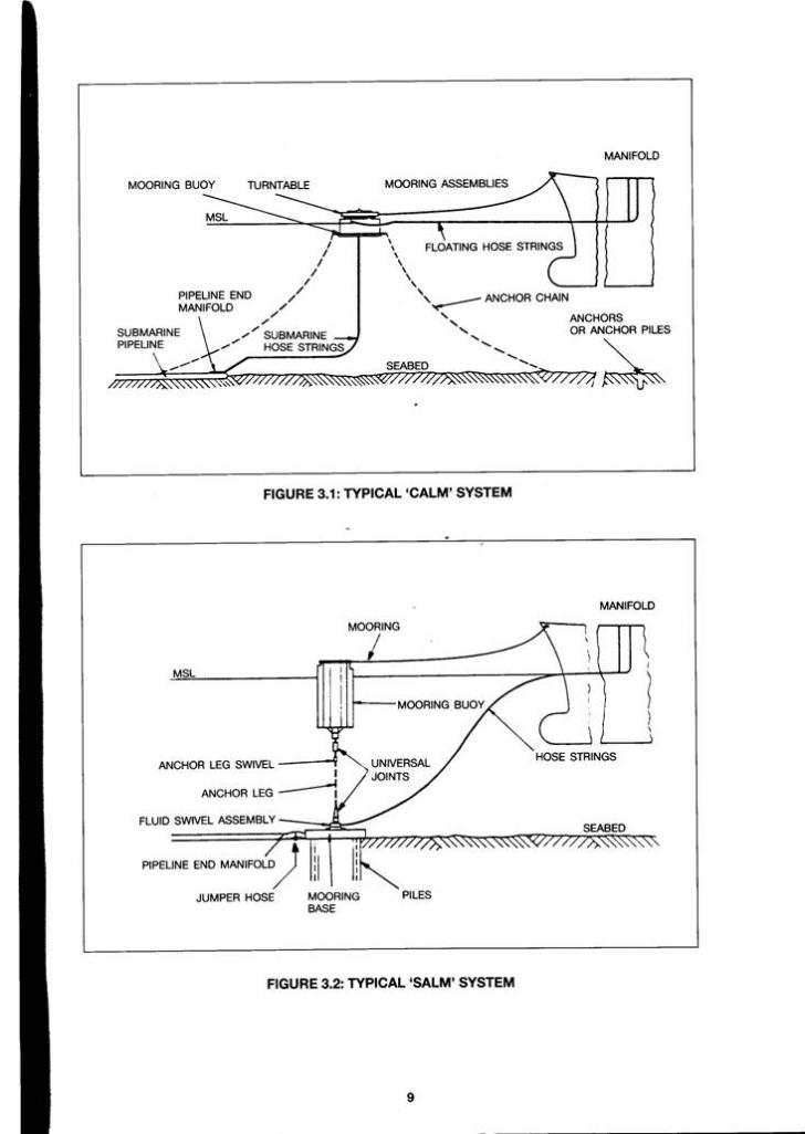
A tvpical CALM system, as shown in Figure 3.1, consists of the mooring buoy, chain and anchor system, mooring assemblies and floating and submarine hose strings.
The mooring buoy is normally steel and has typical dimensions of 12 m diameter and 5 m height. The buoy body provides the necessary buoyancy to keep the system afloat and this is accomplished by watertight compartments located in the outer buoy body. A rotating deck or turntable is mounted on of the buoy body and is designed to transmit mooring forces from the mooring assemblies through buoy to the anchor chains. The turntable carries the fluid piping which connects to the fluid swivel by located in the centre of the buoy. The swivel assembly consists of separate concentric chambers, the number of which depends on the number of fluids to be pumped through the buoy. The piping is also connected to the floating hose strings outboard of the buoy.
The CALM anchoring system consists of 4 to 8 anchor chains, extending from the buoy body radially out and terminating at firmly embedded anchors or anchor piles. Since the anchor chain system is a spring‑type system which has to withstand mooring forces, and thereby station the SPM, each anchor system must be designed for the specific location.
Vessels are moored to the CALM by one or more hawsers attached to the turntable. Hawsers are normally made of synthetic fibre with dimensions depending on tanker size and local operating conditions.
The floating hose strings connect the overboard pipework of the turntable with the manifold of the moored tanker. Floatation is externally attached or built into these hoses. The hose string length is determined by mooring equipment, tanker size and manifold location.
The submarine or under‑buoy hose strings form the connection between the fluid swivel assembly on the buoy and the submarine PLEM (Pipeline End Manifold). Due to the lateral and vertical displacement of the buoy in response to sea conditions and mooring forces, the length and configuration of the under‑buoy hose strings has to be such that, at the maximum possible distance between buoy and PLEM the hose strings are not over stressed and, at the minimum distance between buoy and PLEM. the hose strings are not damaged due to kinking or bottom contact. Optimum hose string configurations are, therefore, of the utmost importance and can only be accomplished by proper engineering. The number of hose strings can vary, depending on the throughput and the number of fluids handled.
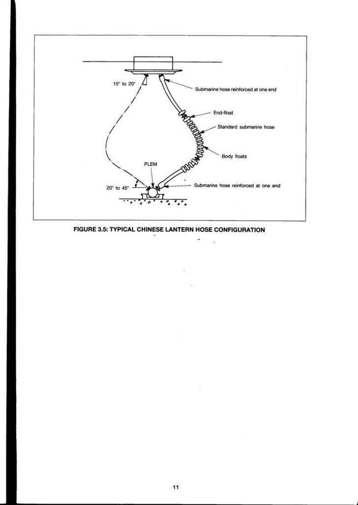
Submarine hoses can be installed in various configurations, which can include lazy S, steep S, or Chinese lantern arrangements. Refer figures 3.3, 3.4, 3.5
3.3 SALM
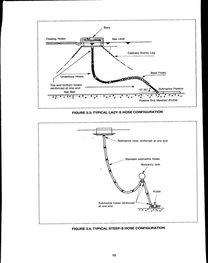
A typical SALM system, as shown in Figure 3.2, consists of a mooring buoy attached to a gravity or pile base by a single anchor leg.
The mooring buoy is normally steel and has typical dimensions of 4 m diameter and 12 m height. Vessels are moored to the SALM by one or more hawsers connected to the mooring buoy. Hawsers are normally made from synthetic fibres with dimension depending on tanker size and local operating conditions.
The SALM anchoring system has two main sections, the base and the anchor leg or riser. The base is the principal structural member which secures the SALM in position. It is designed to carry the horizontal and vertical forces which result from the mooring loads. The single anchor leg is usually a large chain with a swivel incorporated to allow buoy rotation and prevent chain torquing. Universal joints are at both ends of the chain to reduce wear.
A fluid swivel is mounted concentrically about the anchor leg either on top of the base or on top of a riser. The fluid swivel permits the passage of fluid while rotating in response to the moored vessel's movements.
The hose strings for the SALM extend from the fluid swivel unit to the moored tanker manifold and are comprised of submarine and floating hoses which should be designed to withstand the bending forces required to rotate the swivel unit. This is typically arranged such that under normal conditions, the hose strings will extend in a gentle configuration from the fluid swivel unit to the surface. Under extreme conditions the hose strings should maintain a satisfactory configuration. The mooring base may be connected to the submarine pipeline either by rigid piping or by jumper hoses from the SALM base to a PLEM.
Section 4.0
Operational Procedures
The following procedures are only a general outline and should be amended to suit particular requirement. All terminals have different operating parameters due to location and design criteria and the following procedures are intended to provide a basis for operating companies to prepare their own specific operating procedures.
A major part of the operation of an SPM entails working from a launch or handling heavy equipment . Whilst the work is usually carried out under the supervision of a berthing master, it is not without danger and precautions should be taken to ensure the safety of the people involved.
4.1 PREPARATIONS FOR BERTHING
Prior to arrival of a tanker, it is essential that a proper line of communication is established between ship and the terminal.
The terminal should provide the arriving tanker with a message advising mooring arrangements, hose connection details and port requirements, including details of any prohibited anchor areas. The message should request details of the tanker's arrival draft, and expected sailing draft, mooring arrangements, manifold sizes, bow to manifold distance, SWL (Safe Working Load) of lifting equipment and ability to comply with international safety and pollution prevention standards in force.
The exchange of information should be made as early as possible, preferably at least 72 hours before
After the exchange of information, the terminal should ensure that the tanker can safely occupy the
SPM Pre‑Berthing Inspection
Prior the berthing of the tanker, an inspection should be made of the SPM, workboats and all an equipment to be used for mooring
the tanker and connecting the hoses. The following describe the inspection checks required prior to berthing.
A schedule of pre‑berthing inspection is also provided in section 5.1.1.
The berthing master and his mooring crew should check that the freeboard and trim of the buoy we correct and if possible board the buoy to check that the hatches are secure. The mooring hawser connections should then be inspected for tightness and damage and the correct operation of navigation equipment established.
For CALM type SPMs the condition of hose connections, valves, pipework and the fluid swivel should be inspected for tightness and leaks and the valves checked for correct setting. The turntable should be checked for free rotation and for any unusual noises from the main bearing or fluid swivel.
If installed, the telemetry and instrumentation required for monitoring mooring load, fluid pressure and temperature and for the operation of valve actuators should be switched on.
In certain circumstances it may be preferable to include inspection of the submarine hoses and PLEM valves during pre‑berthing inspection. This will depend upon the frequency of the use and operational circumstances of the SPM.
Hoses
The floating hoses should be inspected by launch to ensure that they are not damaged and are streaming freely. Careful attention should be paid to the hose pick‑up arrangements to ensure that they are not fouled.
If applicable, hose marker lights should be checked to ensure that they are operational.
For SALM type SPMs the distance between the point of submergence of the hose strings and the buoy should be checked against the optimum design distance to verify that the submarine hose configuration is correct and that submarine hose 'wrap‑around' has not occurred.
Hawsers
The hawsers should be carefully inspected by launch to check for damage. The chain support buoys and pick‑up ropes should be checked to ensure that they are streaming freely. A simple way to do this is to pull the pick‑up rope with the mooring launch so that the pick‑up rope and mooring assembly is stretched. Careful attention should be paid to the connection between the pick‑up rope and the chafing chain.
If two separate hawsers are to be used in the mooring during mooring activities, the one furthest away from the floating hoses should be tied back on the SPM so that it is clear until required.
Ancillary Equipment
The following ancillary mooring equipment should be inspected for condition prior to mooring:
‑ Wires
‑ Shackles
‑ Messengers
‑ Stoppers
The following ancillary hose connection equipment should be similarly inspected for condition:
Reducers
Gaskets
Bolts
Tools for connecting hoses to reducers and manifold
Assorted strops and shackles
Hose snubbing ropes
Chain blocks
Pressure gauges
Oil spill clean up material
Hose pick‑up arrangement
Shipboard Measures
Prior to approaching the buoy, the following shipboard measures should be taken:
A pilot ladder and/or accommodation ladder should be made ready, in accordance with SOLAS, for access on the side advised by the berthing master. The location should be away from that required for hose handling.
If pilot embarkation is by helicopter, safety precautions should be taken on board the tanker in accordance with ICS recommendations.
Power should be on the winches on the forecastle and to the derricks or cranes at the ships manifold which should be made ready to lift the ancillary mooring and hose handling equipment. Hoses will generally be connected on the port side of the tanker, amidships, and the manifolds should be made ready. Local conditions sometimes require that hoses should be connected on the starboard side, but this is unusual. Notification will, in any case, be given from the terminal.
A messenger line should be placed on the forecastle head, this should be either a 24 mm dia. nylon rope, 90 in long, or alternatively a rope of equivalent strength. A large hammer and fire axe should also be available forward.
4.2 MOORING
A typical mooring operation is as follows:
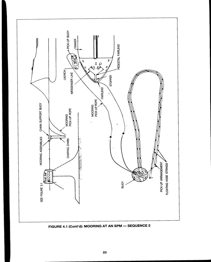
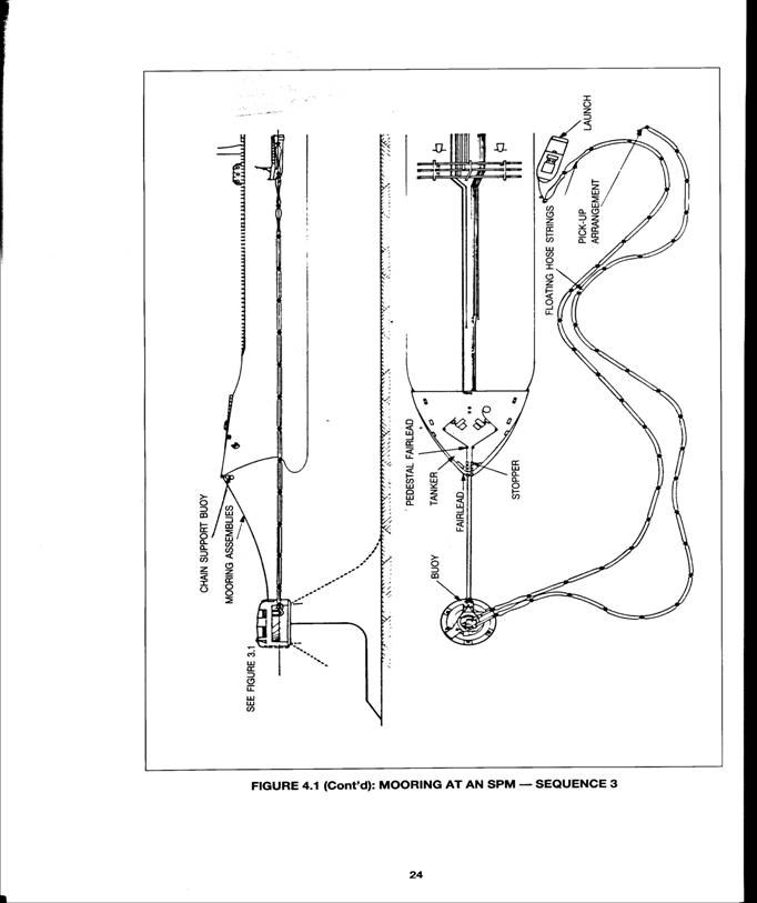
When contact is made with the approaching tanker, normally by VHF (Very High Frequency) radio, the berthing master should confirm the mooring arrangements and hose connection details, and the ship master should confirm that trial engine manoeuvres have been successfully completed. The mooring plan should be made after the first exchange of information as described in Section 4.1. Recommended mooring procedures are shown in Figure 4.1.
The berthing master and his assistant should board the tanker prior to the tanker's approach to the SPM and should bring on board the required ancillary equipment for mooring and hose connection. One of the mooring launches will be used for boarding and it is preferable that the ancillary equipment is made ready for a single lift by the tanker's derrick. The mooring launch should return to the SPM to await the tanker's approach.
Meanwhile, the tanker master, using the advice of the berthing master, should carefully study the wind, waves and current to determine the best approach direction. The approach should be made from the direction in which the tanker can best be handled at very slow speed and can be best held stopped in the water. The berthing master's assistant should be stationed on the bow during the approach to the buoy, and for the full duration of the mooring operation he should remain on the forecastle in radio contact with the bridge, until he is satisfied that the vessels securely moored.
In order to avoid damage to submarine pipelines and SPM anchor chains, ships anchors should not be dropped within the manoeuvring area except in extreme emergency. The berthing master, or his assistant, should check and ensure that the anchors are fully home and secured before making the final approach.
During the approach the mooring equipment should be prepared on the tanker's bow according to the way in which the tanker is to be moored.
At this time, a mooring launch should tow the floating hose strings away from the tanker's direction of approach in the form of a bight to ensure that the hose strings are kept clear of the vessel's propellers during berthing. A second launch should assist with the actual mooring operation. In some locations, it may be possible to use one launch to perform both functions.
The final approach should never be made until the launches, the mooring equipment, and forecastle area arrangements are confirmed as being ready and suitable by the berthing master's assistant.
In making the final approach, the tanker should take a course which will avoid contact with the SPM, moorings and hose strings. If the tanker overshoots and the mooring has to be suspended, the tanker can then pass clear in safety and will be able to manoeuvre for a second approach.
At a convenient safe distance from the SPM, the berthing master should advise the ship's crew to lower a messenger line through the fairlead which is to be used for the mooring. The fairlead should be as close to the centre line of the tanker as possible. The messenger line should fall aft from the bow so that the launch can come alongside without having to manoeuvre under the bow or be affected by a bulbous bow. If a bow thruster is fitted, it should be stopped during this stage of the operation.
The launch should take the messenger line and connect it to the mooring pick‑up rope. If two separate mooring assemblies are to be used, the first one to be connected will be the one nearest to the floating hose strings. The pick‑up rope is commonly 80 min dia. and 150 in in length. If pick up buoys are fitted to the pick‑up rope, they should be disconnected when the messenger is attached and stowed on the launch.
When the messenger line has been connected, the tanker should manoeuvre to within 50 in of the SPM. As soon as the launch is clear, the messenger line should be winched on board the tanker as quickly as possible. The pick‑up rope should be transferred to the winch and heaved in until the chafing chain passes through the fairlead and reaches the required position, it is essential that the lead of the pick‑up rope between the fairlead, through the bow stopper, and to the winch, should be as direct as possible. Care should be taken when winching in the pick‑up rope to ensure that there is always some slack in the mooring assembly. The use of the pick‑up rope to heave the vessel or maintain the vessel's position is dangerous for the personnel involved in the operation and should never be attempted. Care should be taken if drum ends are used to heave the pick‑up rope and mooring assembly on board.
Consideration should be given, if it is practical, to using a self‑spooling drum for the pick up arrangement. This will necessitate emptying the drum of other rope prior to arrival.
Once the chafing chain is in the correct position, it should then be secured to the tanker in the stopper as expediently as possible and before the moorings come under tension. If two mooring assemblies are to be used the second chafing chain should be heaved on board using the same procedure and secured as close to the other as possible. Both mooring assemblies should be the same length when secured.
Whilst the mooring assemblies are being connected, the tanker should remain stopped relative to the buoy with the mooring assemblies slack. It can be very dangerous to the mooring crew if the mooring assembly is allowed to become tight before the connection is completed. When the connection is made, the tanker should be allowed to settle back slowly on the mooring assemblies.
The mooring operation can be carried out by day or night. During night berthing, the launches should assist the berthing master by indicating the location and direction of the floating hose strings and mooring assemblies by illuminating them with their search lights. During the final approach, the berthing master should use the searchlights to gauge his distance from the hoses and the SPM. Good communications between the berthing‑master, his assistant on the bow, and the launches is of particular importance during night berthing.
Whilst the tanker is secured to the SPM, the berthing master should ensure that suitable precautions are taken to monitor the vessel's position relative to the buoy to prevent the vessel from riding up to the buoy or yawing ‑excessively. It may be necessary to station an experienced crew member equipped with radio communications in the fore part of the vessel. The tanker's engines should remain on stand by and ready for immediate use at all times. If tugs are used in the berthing operation or in accordance with 8.1.3, proper preparation should have been made for securing the tugs and sufficient manpower should be available.
4.3 HOSE HANDLING
Hose handling should always be carried out with the hose string de‑pressurised, or under slight internal pressure. The berthing master's assistant will advise the tanker crew on hose handling procedures.
4.3.1. Hose Connection
After the vessel is securely moored, the berthing master should instruct launch to tow the ends of the floating hose string to a position underneath the tanker crane or derrick. If more than one hose string is to be connected, one hose string should be handled at a time. It is essential that the hose string nearest the tanker is connected first and in manifold order from forward to aft. The hose connection should be made in accordance with the following procedure.
Preferably the vessel's hose lifting crane or derrick should be positioned such that the hose can be lifted vertically outboard of the side of the vessel.
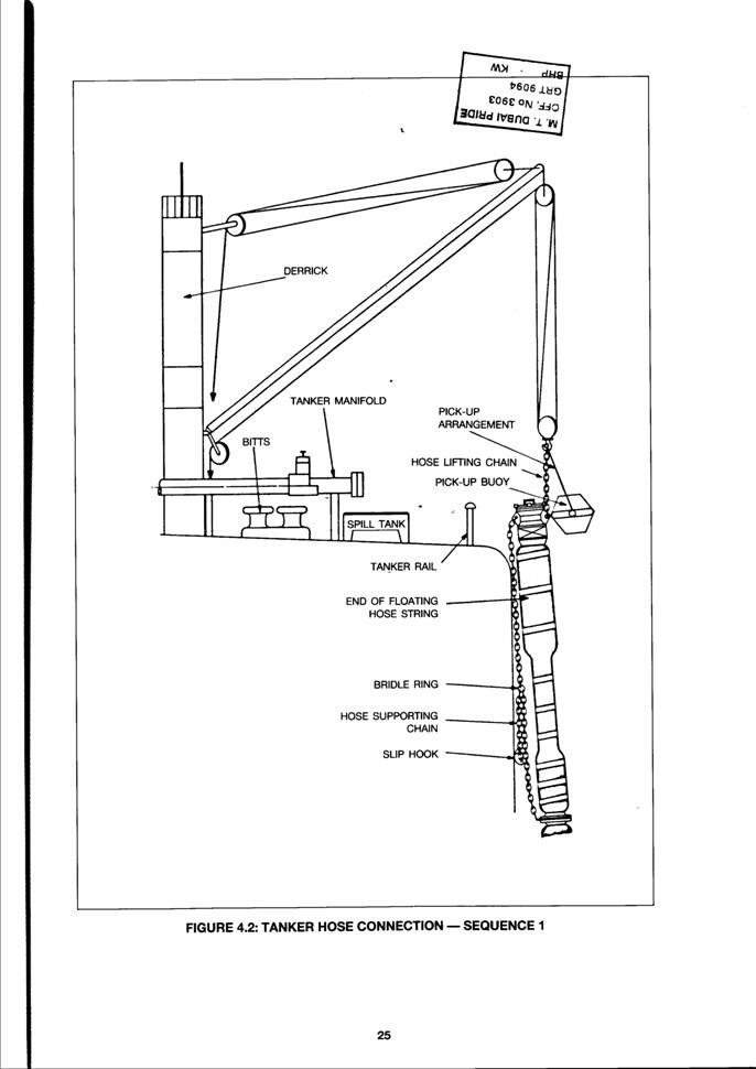
The tanker crew should lower the crane or derrick hook and the launch crew should insert the hook into the hose lifting chain. The hose should then be lifted out of the water to enable the pick‑up buoy to be disconnected at the tanker rail as shown in Figure 4.2
Sequence 1.
At this time, the condition and security of the various hose lifting gear components should be visually inspected for excessive wear, damage, or poor connections.
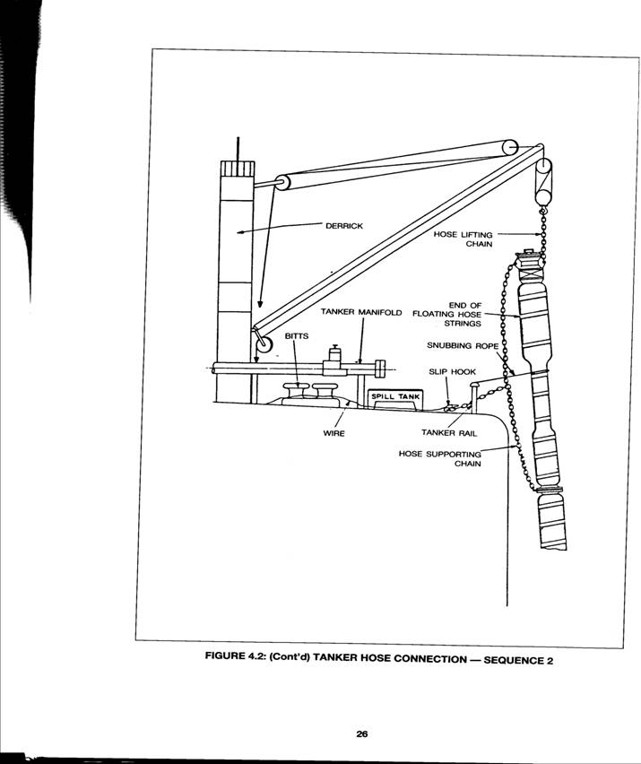
The hose should then be lifted to a sufficient height to enable the hose supporting chain to be attached and to facilitate hose connection. When the hose is at the correct height, a wire should be connected to the slip hook and fastened with a minimum of slack to suitably located bitts as shown in Figure 4.2 ‑Sequence 2. The method indicated is commonly used but other arrangements, including the use of chain secured directly to the bitts, have been developed. Terminals should determine the optimum method for their location.
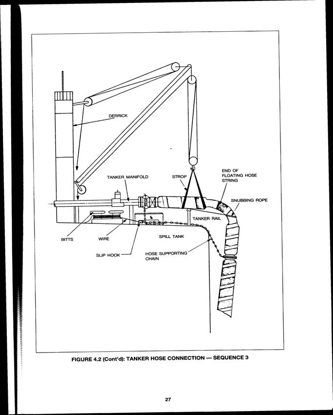
The hose should then be lowered to transfer the full weight to the hose supporting chain. The derrick can be adjusted inboard. A snubbing rope positioned around the hose and secured to the tanker rail will assist lining up the hose to the tanker manifold and preventing lateral movement during connection. The height of the hose should be sufficient to allow the hose tJ be bent over to the tanker manifold and for the hose and manifold flanges to be aligned. It is prudent to allow a little extra height as it is easy to slacken the wire a little to achieve accurate alignment.
The hose should then be bent down so that the blind ‑flange on the hose can be removed. Before removal a check should be made to ensure that the line is de‑pressurised and a spill tank or drip tray should be positioned to contain any leakage. The hose should then be connected up as shown in Figure 4.2 ‑ Sequence 3. The hose should be connected to the manifold using bolts or acceptable quick coupling devices.
All bolted connections should use the full number of bolts and tightening should be in a diagonal sequence. High quality gaskets should be used.
If the end of the floating hose string is sealed by a butterfly valve, the valve should be locked in the open position during cargo transfer operations. Valves should never be operated when oil is flowing through the hoses in order to avoid surge pressures.
When the hose connection has been made, a strop should be connected to each hose string and hooked onto the derrick as shown in Figure 4.2 ‑Sequence 3. The strops should be used to achieve the best radius configuration. The snubbing ropes should be left in position to minimise lateral movement of the hoses induced by swell.
During the hose lifting and connection operation, care should be taken to ensure that the weight of the hose string is not taken off the support chain by other than the prescribed lifting gear. In particular, the strop should not be used to take the full weight of the hose string to adjust the support chain.
Hose Disconnection
The disconnection of hoses can be dangerous and care should be taken to ensure that the hoses secured to the tanker or derrick at all times, until they are lowered to the sea. Before disconnection , , the hoses, they must be flushed or emptied and depressurised. The manifold valves and hose valves, if fitted, should be closed to the satisfaction of the berthing master or his assistant.
It is essential, if more than one hose string is used, that the hoses are disconnected in sequential order from aft to forward. This will avoid the hoses fouling each other when they are lowered to the sea.
To disconnect each hose, its weight should be taken on the derrick at the strop and the manifold bolts disconnected. Care should be taken to stop the hose moving when the bolts are removed and this is most easily done by securing a tine around the hose near the flange and fastening it to convenient bitts. When disconnected, the hose should be blanked off using a blind flange and a good quality gasket. All bolts and nuts must be properly tightened to prevent oil leakage when the hose string is later pressurised.
When the blind flange is secure, the derrick hook should be transferred from the strop to the hose pick up arrangement. The hose should be slowly lifted to the vertical, while slacking away on a steadying rope attached near the blind flange. When the hose hangs vertically and the derrick has the full weight, the snubbing rope and supporting chain may be disconnected. The hose should be lowered until the pick up arrangement is level with the tanker rail. The marker buoy may be reconnected to the pick up arrangement at this time.
A line should be passed through the pick up arrangement and secured to the tanker so that it can be used as a slip rope. Care should be taken to ensure that the slip rope is long enough to lower the hose to sea level. The hose string should then be hung off the slip rope with the blind flange at deck level and the derrick hook disconnected. If more than one hose string is used the other hose strings should be disconnected using the same procedure.
The hoses should remain in this position until the tanker is ready to depart. Whilst the tanker is securely moored the hoses should 6e slowly lowered (aft hoses first) to the launch, so that they can be towed clear. Alternatively, the hoses may remain hung off in this manner until the moorings are cast off. The hoses can then be lowered without the need of a launch and will not foul the ship's propeller. It is an unsafe practice to keep the hoses connected in whatever form after the mooring ropes have been released.
4.4 CARGO OPERATIONS
The basic procedures for cargo handling at SPMs are the same as those for a conventional berth.
Since good communications are of the utmost importance for safe cargo handling, a reliable communications system, including a secondary stand‑by system, should be established and tested.
Prior to a tanker arriving to load or discharge a proper exchange of information should be made between the terminal and the tanker. This should include a check on the ability of the tanker to comply with the international tanker safety and pollution prevention standards.
Upon arrival of the tanker, it should be inspected as to it's compliance with industrial standards, both from a technical as well as from an operational point of view.
The loading or discharging plan, as well as the arrangements for emergency shut down of cargo operations, should be agreed between the berthing master and the responsible tanker officer during a pre‑transfer conference and recorded in writing.
The ISGOTT Ship/Shore Safety Check List should be completed, and checked and signed at regular intervals throughout operations.
A joint ship‑shore pumping and valve closing regime should be established and maintained to avoid pressure surges.
Where automatic/remotely controlled valves are used to stop or divert flows, their closing characteristics, together with the planned discharge/loading rate, shall be laid down and checked against established maximum permissible surge pressures in the shore and ship pipeline system.
Cargo transfer operations should not commence until the ship's officer on duty and the berthing master are satisfied and have agreed that the hoses are correctly connected and that all necessary ship, buoy and terminal valves have been set for receiving or discharging cargo, and that the communication link between ship and shore is established and functioning.
Cargo transfer should begin slowly until it has been verified that oil is reaching the designated tanks and that the whole system is operating satisfactorily. The hose strings and the area around the mooring buoy should be inspected from the mooring launch for evidence of leakage. When it has been firmly established that the total system is operating correctly, the pumping rate may be increased to the maximum rate as specified by the shore station or the ship as the case may be. A member of the tanker crew, equipped with radio communications, should be continuously on watch on deck. Sufficient crew should remain on board to deal with the operation and security of the tanker. During cargo operations periodic inspections should be made of the manifold connection, the entire hose system, and the areas around the ship and mooring buoy. At regular intervals the pressure at the manifold and the quantity of cargo transferred should be recorded by both ship and shore and the figures compared with each other. Any marked discrepancy between quantities should be investigated immediately.
Upon completion of cargo transfer, it is essential that the ship's valves remain open until oil flow has ceased completely. The berthing master must wait for confirmation from shore before directing that the ship's valves should be closed.
4.5 BALLAST OPERATIONS
Ballast control at SPMs is important. If tankers are properly fitted with segregated ballast systems or suitable clean ballast systems they should always commence ballast operations concurrently with cargo transfer operations in order to avoid being secured to the SPM in a light‑ship condition. Tankers secured to SPMs in a light‑ship condition can be difficult to control. This condition should be avoided.
For tankers which are unable to handle ballast concurrently with cargo, it may be beneficial to increase the ship's draft in poor weather conditions by suspending cargo discharge to take on ballast or by suspending ballast discharge to take on cargo as appropriate. At all times international tanker safety and pollution prevention standards should be complied with.
4.6 UNMOORING
4.6.1. Assisted Unmooring
Before unmooring, the connection between the pick up rope and the chafe chain should be checked and replaced as necessary. All unnecessary ancillary equipment should then be loaded onto the mooring launch and non‑essential personnel should be disembarked. The mooring launch should come alongside in the vicinity of the manifold and the hoses should be lowered, in turn from aft to forward, and passed to the launch. The launch should then tow the hoses away from the tanker and hold them in a bight away from the line of departure. As an alternative, if conditions permit, the rail hoses can be tied back to the SPM thus freeing the launch for other duties.
The weight should be taken off the mooring assemblies, if necessary, by an ahead movement on the tanker's engine. The pick up rope should then be heaved on the winch and the chafing chain let go from the bow. The pick up rope should then be slowly paid out through the fairlead. If two mooring assemblies are used they should be let go together if possible, but if they have to be disconnected separately, the one nearest the floating hose should be let go first. The pick up rope should be slow1N slackened until the chafing chain is in the water. Care should be taken to avoid lowering the mooring assemblies across each other or over the floating hoses. Whilst the pick up ropes are being lowered, the tanker should come slowly astern until it is clear of the SPM. When the tanker is clear, the launch should come alongside to receive the ancillary equipment and to disembark the berthing master and his assistant.
When the tanker has departed, the berthing master should supervise the disconnection of the mooring assemblies from the SPM, if this is to be done, or alternatively, check that they are in good condition. A similar inspection of the floating hose strings and the SPM, should be made.
All monitoring and telemetry equipment on the SPM should be switched off, as necessary. The navigational equipment should be checked and the SPM left in good order.
The berthing master, assistant and launches are then free to stand down.
Unassisted Unmooring
Before unmooring, the hoses should be disconnected and hung off at the tanker's rail. Two seamen should be stationed at the hand off point under the supervision of the berthing master's assistant in readiness for letting go. The hose slip ropes should be slowly slackened and the hose string lowered to sea level as described in Section 4.3.2.
The weight should be taken off the mooring assemblies using the tanker's helm and engines.
On the forecastle, the pick‑up ropes should be heaved on the winch and the chafe chain let go from the bow. The pick‑up rope should then be lowered slowly. When the chafing chain reaches sea level and the weight is off the pick‑up rope it should be cast‑off from the tanker and the tanker should slow come astern to clear the berth. If two mooring assemblies are used, they should be let go together if possible, but if they have to be disconnected separately, the one nearest the floating hose should be let go first. Care should be taken to avoid lowering the mooring assemblies across each other, or over the floating hoses.
As the tanker gains sternway and at a time when the floating hoses cannot foul the ship's propeller, the hose strings should be cast off.
When the tanker is clear, the launch should come alongside to receive the ancillary equipment and to disembark the berthing master and his assistant.
4.7 SAFETY
When a tanker is secured to an SPM, the recommendations which are given in the International Safety Guide for Oil Tankers and Terminals (ISGOTT) should be followed. This guide makes recommendations for practices to be adopted by tanker and terminal personnel to ensure safety in operations relating to the carriage by sea and the handling on tankers and at terminals of crude oil and petroleum products.
Good communications should be maintained at all times between the ship, shore terminal and mooring launches.
If the berthing master considers it necessary he may require that an experienced crew member equipped with radio communication is stationed in the fore part of the vessel.
A member of the tanker crew should be continuously on watch on deck. Sufficient crew should remain on board to deal with the operation and security of the tanker.
The agreed ship‑to‑shore communications system should be maintained in good working order.
A responsible member of the terminal organisation should be on continuous duty at the shore end of the ship‑to‑shore communication system.
At the commencement of loading or discharging, and at each change of watch or shift, the responsible officer and the terminal representative should confirm with each other that the communication system for loading and discharging control is understood by them and by personnel on watch and on duty.
The stand‑by requirements for normal stopping of shore pumps on completion of loading and the emergency stop system of both tanker and terminal should be fully understood by all concerned. I I
During cargo transfer, the hose strings and SPM should be regularly inspected, and monitored for leakage.
The hose strings in the vicinity of the tanker manifold and tanker rail should be regularly inspected by the berthing master or his representative for distortion and chafe.
Regular inspections of the mooring assemblies and hose connections should be carried out and defects such as loose shackles made good immediately. It is important that such inspections are made immediately prior to letting go of the hose strings and the mooring assemblies.
Pressure, temperatures and cargo quantity checks should be made at regular agreed intervals and the, results compared between the tanker and shore. Any variances should be investigated immediately.
A mooring launch should be available whilst the tanker is in the berth.
Instrumentation is sometimes used on SPMs. The use of telemetry systems enables remote monitoring of many aspects of SPM operations to be carried out. Probably the most important monitoring equipment is that used to measure mooring loads. The mooring loads are normally transmitted by telemetry to the shore terminal where they can be recorded. Additionally, the signal can be transmitted directly to a portable receiver in the berthing master's possession. Such instrumentation can be used to give early warning of reaching maximum allowable mooring load conditions and to enable tankers to safely use the SPM to maximum berth occupancy, particularly during changing weather conditions. It is recommended that terminals have suitable environmental parameters in place to ensure that operations can be carried out in a safe manner. Suitable equipment should be available to enable these parameters to be measured.
4.8 POLLUTION
The risk of oil spillage and pollution will always be present as long as oil is being shipped and stored. However, most accidents are not caused by natural events, but by human error and technical failure. This means that spills can be prevented by appropriate instruction and training of personnel, which is far more effective than fighting pollution after spillage has occurred.
SPM facilities do not present a greater pollution risk than a conventional alongside berth. The possibility of spillage however clearly remains and therefore at every location a contingency plan for fighting pollution should be available. There is world‑wide agreement as to the rights and duties of national governments to protect their coastal areas against environment degradation. In case no national government supported contingency planning exists, industry should take a lead to promote such a plan for dealing with the first steps of pollution resulting from its activities.
Advance consultation and agreement between government and industry on action programme is an essential requirement, as any effort to fight oil pollution without the proper organisation and support will achieve very little, when a national emergency condition occurs.
Section 5. 0
Inspection Schedules and
Procedures
To ensure efficient, reliable and safe operation of an SPM terminal and its components it is important to perform inspection and routine maintenance tasks on a regular basis.
This section provides guidelines for setting up inspection schedules and procedures for CALM and SALM type SPMs and describes the maintenance tasks which should be performed during inspection.
5.1 INSPECTION SCHEDULES
The scope of the Inspection Schedule and the frequency of the inspection of individual components should be based on the best available information concerning the SPM equipment and the particular conditions at the SPM and should be modified on the basis of actual operating experience.
Care should be taken during inspections, including when diving, to ensure that the SPM is gas free in all areas, including the well of the buoy.
The following schedules for pre‑berthing inspection and weekly, monthly half‑yearly and yearly inspection are recommended as a guideline. The scope and frequency can be altered to suit the requirements of individual terminals. Reference should be made to the manufacturer's manuals for specific details.
Pre‑berthing inspection as described in Section 4.1.1 is presented here in schedule format for the sake of completeness. Pre‑berthing inspection is performed primarily to ensure that no damage has occurred to the components of the SPM system since the last inspection or berthing. Circumstances at the terminals, such as high berth occupancy, may ~e the cause for performing this inspection on a daily
basis.
Weekly, monthly, half‑yearly and yearly inspection schedules, and the associated maintenance, are intended to reduce the incidence of component failure and costs resulting from unscheduled down‑time. As a result, the life of the SPM facility and its components can be increased and its reliability improved.
The following inspection schedules list activities common to both types of SPM except where otherwise stated. Items requiring divers are marked (D).
5.1.1 Pre‑Berthing (See figure 10.1)
Check for oil spillage or leaks, whilst at the normal working pressure.
Check that trim and freeboard of buoy are correct.
Board buoy and check:
Mooring connections.
Security of hatches.
For signs of damage to buoy.
Hose connections. CALM ONLY
For security of pipework. CALM ONLY
For signs of leakage from product swivel, rubber expansion pieces, or other piping
components. CALM ONLY
That valves are operable and in the appropriate position. CALM ONLY
Pressure gauge readings. CALM ONLY
For unusual noise from bearing or product swivel, or loss of free movement. CALM ONLY
Telemetry systems
Lights are functioning correctly.
Inspect hawsers and pick‑up lines for damage and fouling.
Inspect floating hoses along their length for damage,‑leakage and fouling whilst at the normal working pressure (see 6.2.1).
Inspection of double‑carcass hose should be in accordance with the manufacturer's guidelines.
In addition, the condition of the connections between the pick‑up ropes and the chafing chains, the chafing chains, chain support buoys and connecting links, hose pick‑up arrangements and tanker rail hoses should be checked. These checks should be performed by inspection from a launch prior to berthing, and subsequent visual checks made from the tanker by the berthing master or his assistant after the tanker is moored.
5.1.2 Weekly
Perform all checks in the pre‑berthing inspection schedule.
Board buoy and perform routine lubrication of:
Main bearing assembly.
Surface fluid swivel assembly.
Valve actuators.
Other auxiliary equipment.
Note: Power greasing is recommended. CALM ONLY.
Sound buoy compartments for leakage.
Check operation of bilge pumps if fitted.
Check buoy fendering for damage. (D)
Check centrewell for contamination. CAUTION: Refer to Section 6.1.2 Safety Precautions. CALM ONLY.
Open bearing cavity drain plugs, rod out and monitor quantity of water. CALM ONLY.
Check condition and lubrication of bogey wheels system. (For CALM's with bogey wheels only.)
Monthly
Perform all checks in the weekly inspection schedule.
Lift mooring equipment onto deck of maintenance boat and check:
Mooring hawsers and hawser‑floats (see 6.2.2).
Chafing chain and check for wear (see 6.2.3).
Chain support buoy.
Hawser thimbles.
Connecting chains and shackles.
Pick‑up ropes and connections.
Lift tanker rail hose onto deck of maintenance boat, or alternatively, inspect by divers, and check:
Tanker rail hose.
Hose pick‑up arrangement.
Butterfly valves if applicable.
Board buoy and perform the following tasks:
Check operation of all valve actuators and valves. (D)
Check all electrical systems.
Check battery boxes are dry and that seals are in good condition. check electrolyte level and
charge or replace batteries as required.
Perform diver visual inspection of submarine hose strings including floats, buoyancy tanks, etc. Measure hose configuration and correct as required. (DJ
Clean marine growth from all anodes. Anodes should be replaced if more than 75% consumed. (D)
Attach strop between turntable and launch, tend hoses and slowly rotate turntable assembly through 360' and listen for bearing noise. Check for hard spots or sluggishness. CALM ONLY.
Check that bearing protection system is intact on both sides of the bearing. CALM ONLY.
Open bearing inspection plates and check for water. CALM ONLY.
Inspect surface fluid swivel assembly and adjust bolts for tightness and record adjustments. CALM ONLY.
Measure chain angles and chain weardown under buoy and adjust as required. CALM ONLY. (D)
Inspect perimeter of mooring base for signs of scouring of seabed, and anchor piles for signs of motion. Remove debris. SALM ONLY. (D)
Inspect submarine fluid swivel assembly for signs of leakage. SALM ONLY. (D)
Inspect base universal joint for signs of wear and security. SALM ONLY. (D)
5.1.4 Half Yearly
Perform all checks in the monthly inspection schedule.
Perform an in‑situ pressure test in accordance with OCIMF Guidelines for the Handling, Storage, Inspection and Testing of Hoses in the Field.
Inspect inside of buoy compartments for corrosion and damage. Examine rubber manhole seals and replace as required. CAUTION: Refer to Section 6.1.2 Safety Precautions.
Repair minor damage to paintwork according to paint specifications.
Measure chain weardown at seabed. CALM ONLY. (D)
Check anchor piles, or anchors, and anchor chain connections including joining shackles where accessible.
CALM ONLY.(D)
Check PLEM. (D)
Check surface fluid swivel. For procedure see Section 5.2.1. CALM ONLY.
Check surface piping and expansion joints. For procedure see Section 5.2.2 CALM ONLY.
Check submarine main swivel. For procedure see Section 5.3.1 SALM ONLY. (D)
Check anchor leg. For procedure see Section 5.3.2 SALM ONLY. (D)
Inspect condition of submerged portion of fenders. SALM ONLY. (D)
Inspect condition of flooding valve. SALM ONLY.
Yearly
Perform all checks in the half‑yearly inspection schedule.
Perform complete inspection of cathodic protection system. The anodes should be cleaned to ensure that they provide maximum protection and anodes should be replaced if 75% or more has been sacrificed. (D)
Remove sand and silt from mooring base and/or PLEM. (D)
Inspect selected areas of the hull for wall thickness.
Check surface fluid swivel oil seals and replace as required. CALM ONLY.
Check surface fluid swivel drive plate for wear and distortion. CALM ONLY.
Inspect selected areas of the pipework for wall thickness. CALM ONLY.
Check main turntable bearing. For procedure see Section 5.2.3 CALM ONLY.
Check anchor chains and anchor or anchors piles. For procedure see Section 5.2.4 CALM ONLY. (D)
5.2 INSPECTION PROCEDURES FOR CALM SYSTEMS
Surface Fluid Swivel
Pressurise system, check swivel for leakage of crude oil, product or lubricants.
Remove test plugs and check for leakage.
Rotate unit and listen for bearing noises from structure close to bearings using an engineer's stethoscope or similar instrument.
Check freedom of rotation of swivel.
Check swivel drive assembly.
The oil seals of the central swivel should be examined and renewed if damaged or as per manufacturer's instructions. It may be desirable to renew the seals even if the swivel has given trouble‑free service. The correct procedure for replacing seals should be in accordance with the manufacturer's instruction book. All bolting of the central swivel should be checked for tightness.
Surface Piping and Expansion Joints
Pressurise the total pipework system and check all flanges and valve actuators for leakage.
Check for excessive movement of pipework in pipe clamps.
Check pipe clamp structures for signs of cracks and distortion.
Check condition and alignment of expansion joints while pressurised.
The rubber expansion joints should be examined internally and replaced if the lining is found to be damaged.
Main Turntable Bearing
Check for noise and free rotation:‑
Attach strop to turntable and mooring launch and slowly rotate turntable through 360'.
Repeat rotation check in reverse direction.
Record position of turntable if any sign of jamming or any noise occurs.
Annually three grease samples of 250gms each shall be taken at the bottom part of
the bearing. These samples, as well as a sample of fresh grease, should be analysed for:
‑ Iron content mg/kg (ppm)
‑ Chromium content mg/kg (ppm)
‑ Magnesium content mg/kg (ppm)
‑ Water content mg/kg (ppm)
As long as the iron content remains below 25,000 mg/kg, there is no need to replace the bearing. According to bearing manufacturers, an iron content above 25,000 mg/kg will accelerate deterioration of bearing and consequently preparations should be made to change out the bearing. In case results from grease analysis should raise concern regarding the condition of the bearing, axial and radial weardown measurements are recommended. Wear in the bearing track system will result in increased internal clearance and in settling of the upper companion bearing structure. Internal bearing clearance can be measured as follows:
Measure axial weardown:
- Remove the lower casing from the bearing ring.
- Rig four jacks spaced equidistant on bulk head location, this to avoid deformation in bearing supporting structure.
In case of a six anchor leg buoy, 3 jacks should be used.
- The total capacity of jacks should be sufficient to safely raise the turntable.
- Four dial gauges should be placed in between each jack underside of the exposed ring.
- Each dial gauge should be preset to zero reading.
- The dial gauge
measurements should be plotted against the hydraulic pressure of the 4 coupled
jacks.
at approx. 5 tonnes, 10 tonnes, 15 tonnes, etc., up to 50 tonnes, depending on weight of turntable.
- Measurements should be recorded whilst jacking up and lowering the turntable. The maximum permissible axial bearing
play depending on size and type of bearing is approx. I mm. Manufacturer's recommendations should be consulted for
more precise value.
Measure radial weardown:‑
- Remove inner protection covers.
- 12 x 30' sections to be marked for positioning jacking procedures around periphery of turntable structure.
- Position No.1 to be set at the centre of the outboard pipework.
- Special tool for jacking to be positioned between turntable centre wall and central pipe, below central pipe bearing
in horizontal position. Horizontal force should be max. 20 tons.
- 2 dial gauges to be fixed on turntable and set against the buoy body.
- No.1 dial gauge to be set opposite and adjacent to jacking position readings in the minus direction.
- No.2 dial gauge to be set on turntable against buoy body at 1800 to dial No.1 for readings in the positive direction, in order
to record relative horizontal movement between buoy body and turntable.
- Procedure for reading set at No.1 position is statutory for all 12 x 30' readings.
- The maximum permissible radial bearing play depending on size and type of bearing is approx. 0.5 mm.
Manufacturer's recommendation should be consulted for more precise value.
- Compare results with any previous reports. Annual test should show a gradual increase as wear occurs. The bearing
should be replaced when the clearances exceed tolerance limits given by the bearing manufacturer.
Check the bogey wheels:‑
- Measure clearance between wheels and rails at eight different points.
- Check the condition of the top and bottom rails and the wheels for signs of wear and flattening.
- Check the security of ties between the rotating arms and arm connector pins.
- If clearances exceed the maximum allowable stated in the manufacturer's manual, it will be necessary to replace worn parts
or take other corrective measures. (For CALM's with bogey wheels only.)
Anchor Chains and Anchors or Anchor Piles
Check anchor chains. (D):‑
- Disconnect anchor chain pendants one by one from buoy.
- Lift the top section of each chain out of the water and inspect chain, chainstoppers and ancillary equipment thoroughly.
From the rate of wear, he probable life of the chains can be estimated and a chain maintenance and replacement
programme established.
- Anchor chain links should be replaced when any chain link diameter is reduced due to wear to 80% of it's original diameter.
Check anchors or anchor piles. (D):‑
Measure the distance from the crown of the anchors to the marker pegs to detect drag. Re‑adjust anchor positions as required. Record anchor positions.
Check areas of the seabed immediately around anchors or anchor piles for signs of scouring.
Anchor flukes and at least half of the crown should be embedded. Jet anchors to sink deeper as required.
5.3 INSPECTION PROCEDURES SALM SYSTEMS
Submarine Main Swivel
Attach strop to end of floating hose string and secure to launch.
Tow hose string around buoy to rotate swivel through 360'. Check that the swivel rotates freely. (D)
Repeat rotation check in reverse direction. (D)
Pressurise system. Check all valves and flanges for signs of leakage. De‑pressurise system. (D)
Measure and record clearance between bumper rails and bumpers if applicable. (D)
Inspect hose arm structure for signs of damage and distortion. (D)
Anchor Leg
Measure chain and shackle components for weardown. (D)
Check chain swivel for free rotation. (D)
Inspect buoy and base universal joints. (D)
Measure and record progress of wear on buoy and base universal joints. (D)
Inspect connection between bar universal joint and main swivel. (D)
Check and record siltation level or scour around base. (D)
Inspect bolted connection of main swivel assembly to base structure. (D)
Section 6. 0
Maintenance and Major Overhaul
Routine or preventative maintenance is essential if sudden failure of SPM components and the resulting unscheduled downtime is to be avoided.
This section provides guidelines for the planning and performance of maintenance tasks.
6.1 PLANNING
Maintenance of an SPM facility may involve downtime and is therefore an expensive operation in terms of lost production. Lost time can effectively be reduced by initiating a planned schedule of work, which takes into account long lead items and the availability of facilities and equipment, well in advance of the actual overhaul period. All work should be carried out utilising a permit to work system.
The frequency of maintenance will vary depending on particular conditions at the SPM facility. Maintenance schedules should be based on manufacturers recommendations and the deficiencies and trends observed during regular inspections. The inspection schedules suggested in Section 5 and the records as outlined in Section 10 should give a good indication of the condition of the SPM and its components.
Factors Influencing Planning
Consideration should be given to the following factors when planning maintenance:
Age and condition of the SPM and its components.
Scheduled shut‑downs of other facilities, e.g. platforms or shore facilities.
Replacement parts required and delivery lead times.
Special tools required and availability.
Estimated total time required for completion of work.
Cost penalties in the event of overrun.
Towing requirements and availability.
Yard facility requirements.
Heavy lift requirements offshore and onshore.
Diver requirements and support facilities. 6.1.2 Safety Precautions
Safety is of paramount importance during maintenance work. The following precautions are recommended:
Buoy compartments, including the centre well, must be ventilated. Before entering check that compartments are gas free and that sufficient oxygen is available. Persons entering should wear a hard hat and a safety harness and should be attached to a 'lifeline'. An assistant should standby tending the other end of the line. Oil spillage in work areas should be properly cleaned up. When compartments are being inspected the turntable should be locked to ensure that access hatches are clear at all times.
Hot work should be in accordance with a hot work permit system. This system should be operated by a responsible person who will ensure that the appropriate areas are gas free and who will impose the particular restrictions required to ensure personnel safety.
Due attention should be paid to earthing points when electric arc welding is carried out. IT IS ESSENTIAL THAT WELDING EQUIPMENT IS NOT EARTHED ACROSS THE BEARING. Stray electric currents can cause severe damage to turntable bearing elements or product swivels.
Lines are usually purged with sea water prior to commencing any work on the product transfer system.
6.2 INFORMATION APPLICABLE TO ALL SYSTEMS
Replacement of SPM Hoses
In general SPM hoses should be brought ashore and tested as part of a preventive maintenance plan. The frequency of onshore testing will vary depending on operating and environmental conditions at the terminal. Testing of hoses periodically and maintaining detailed records will assist in determining change out frequency. Certain types of ‑hoses such as First Off the Buoy and Tanker Rail hose tend to have a lower service life than other types.
Recommended procedures for the replacement of CALM type SPM floating and submarine hose strings are shown in Figure 6.1 and 6.2 respectively. Procedures for the replacement of SALM type SPM hose strings are shown in Figure 6.3.
Replacement of Mooring Hawser and Pick‑ Up Rope Assemblies
At the present time no universal method exists for determining the remaining useful life, or residual strength, of a used mooring hawser. It has been established that cyclic loads, physical damage, and ageing can contribute to loss of strength.
At most SPM terminals one or more of the following methods are used to determine when mooring hawsers should be replaced:
Visual Inspection
Evidence of severe external abrasion especially near splice locations and eyes.
Evidence of severe abrasion between strands.
A significant number of strands cut or pulled out.
Evidence of damage to the inside core of the hawser such as necking.
Number of Ships/Length of Service
‑ Limits for maximum service life expressed as a number of ships or months unless visual inspection results in earlier retirement.
A combination of visual inspection and number of ships/length of service is probably the best method to use until more precise methods are developed. Break testing of used hawsers with recorded service histories may provide a rational basis for adjusting replacement criteria.
Replacement of Chafing Chains
Chafing chains should be replaced when any chain link diameter is reduced, due to wear, to 90% of its original diameter.
6.3 INFORMATION PARTICULAR TO CALM SYSTEMS
Replacement of Main Turntable Bearing
Noise during rotation, signs of jamming or other signs of wear indicate a faulty bearing. Bearing failures may be due to any of the following reasons:
Lack of lubrication.
Overloading in excess of the design limits caused, for example, by vessel collision or excessive hawser loading.
Stray electrical current caused by incorrect earthing during welding operations.
Insufficient protection against water ingress.
Incorrect bearing installations.
When a failed bearing is dismantled, it is important to inspect all surfaces and identify the root cause of failure. If possible, improvements should be made to avoid recurrence.
In general, a turntable roller bearing requires the exchange of the entire bearing. In cases where the bearing is mounted by a metal‑to‑metal facing and only machining of the horizontal faces is required. the repair may be undertaken offshore. Overhaul of bearing resin surfaces must be undertaken on a barge or onshore where controlled conditions and facilities are available.
Following the removal of the turntable and the old bearing the first stage in replacing a conventional bearing is to place the new bearing onto the support ring of the buoy body.
The bearing should be levelled and centred by the adjusting screws and guiding pins, checking that:
Its centre is concentric to the axis of the central swivel unit.
Its plane is perpendicular to the axis of the central swivel unit.
The bearing is within flatness tolerances as specified by the manufacturer.
Where applicable, the foundation resin should be applied after alignment. The bearing fastening bolts can be installed and pre‑tensioned after a 24‑hour resin curing time. Pre‑tensioning of the fastening bolts to values specified by the manufacturer is preferably done by hydraulic tensioning jacks although a torque wrench may be used where access. is a problem. It should be noted that the torque wrench method is far less reliable.
During installation, the attendance of a bearing specialist is recommended. In the second stage the turntable should be placed on top of the buoy onto adjusting screws. The bearing grease holes must correspond with the connections in the support structure. The same procedure for the alignment, grouting and fastening of the bearing to the buoy body should be followed. Grease pipes should bc checked and grease lines connected. The bearing should be greased whilst rotating the turntable until a grease collar appears at the seals.
Surface Fluid Swivel
Dismantling of the surface fluid swivel and the replacement of seals should only be attempted in‑situ in good weather and calm seas.
Dismantling may be required if product or contaminated grease is seen to be leaking from the swivel. From the source of the leak it will be possible to decide whether partial or total dismantling is required. Leakage of uncontaminated grease may be due to excessive lubrication. In this case dismantling is not required.
Renewal of seals should be performed with reference to manufacturer's manuals. Before any component is removed, reference marks should be made on convenient non‑critical surfaces. Upon removal, all components should be cleaned and inspected and all defects noted. All machined surfaces should be coated with grease and critical surfaces protected.
Turntable and Ancillary Equipment
During periods of routine maintenance, a thorough inspection of all the components on the turntable assembly should be made. Particular attention should he paid to the condition of:
Mooring assemblies.
All flexible joints in the turntable piping.
Piping, pipe supports and valves.
Pressure gauges.
Navigation aids and electrical system.
Turntable brake if applicable.
Chain tensioning and lifting equipment if applicable.
Overboard pipe swivels, if applicable.
Depending on the results of the inspection, repairs and renovation, including any cleaning and repainting of steel surfaces, should be performed.
Anchor Chains
The progress of wear on anchor chain pendants and joining shackles can be judged from previous results of inspection checks for weardown. An assessment of the need for the replacement of chain shots and other fittings such as shackles can then be made (see 6.2.3).
It is of paramount importance for the proper working of the SPM facility that the buoy is correctly positioned with respect to the end of the submarine pipeline and that the anchor chains are correctly pre‑tensioned.
The position of the buoy, should then be checked with a plumb line against a fixed reference point on the seabed or by using other suitable instrumentation such as electronic position fixing systems at slack tide. The pretension in the chains should be monitored by measuring the inclination of the chains to the horizontal using an angle indicator as shown in Figure 6.4. The buoy position and the measured angles should be recorded for comparison with design values and subsequent measurements. Any substantial deviations beyond design tolerances should be corrected as soon as possible.
If the angle is too great then the chain pendant is too slack. This may be due to the following causes:
Straightening of pendants under loads greater than those applied during laying.
Chain failure.
Dragging of anchors.
If the angle is too small there is too much tension in the chain pendant. This may be caused by settling of the pendant in the mud. This situation needs prompt attention, because the available lifting capacity may be insufficient to lift the chain from its housing if it is left too long. Marine growth or corrosion may prevent the chain from being lifted from its housing and therefore chains should be lifted regularly.
The following tolerances in the angle of pretension are normally permissible for six or eight pendant systems:
Between two chains at a watertight bulkhead the difference not to be more than two degrees.
Between any two chains not more than four degrees.
The average inclination of all chains should lie between the design angle and the design angle minus two degrees and the inclination of no chain should exceed the design angle plus two degrees.
Buoy
Minor overhauls may be possible with the buoy in‑situ, but major overhauls will require the buoy to be dry‑docked The interval for major overhaul will depend on terminal usage but can be assumed to be in the region of 10 years.
In preparing a suitable work site, such as a drydock or other area with crane lift capacity, the manufacturer's layout drawings should be carefully studied. The blocks on which the hull will rest must be positioned so that the hull is supported on the watertight bulkheads, and the blocks must be of sufficient height to allow clearance for the cargo piping extending below the bottom and to allow painting of underside platework. Care should be exercised to ensure that the anodes on the bottom of the hull are kept clear of the docking blocks.
Removal of the buoy from the terminal site can be achieved by either lifting the buoy onto a barge or by towing to a dry dock facility.
Buoy Towage
During towing, a minimum unobstructed water depth of 4.5 m is normally required but this should be checked against the manufacturer's drawings. Towing cables should never be attached to any part of the turntable assembly. Towing cables should incorporate a stud link chain to fit chain stoppers on the buoy. A typical towing configuration is shown in Figure 6.5.
PLEM
Unless damage has occurred or leaks or excessive corrosion are observed, it should not be necessary to remove the PLEM or any of its components from the sea bottom. Other maintenance is limited to regular checks for bolt tightness.
6.4 INFORMATION PARTICULAR TO SALM SYSTEMS
Minor leg maintenance may be possible while the SPM is in‑situ. Major maintenance of the buoy, anchor leg and main swivel will require the components to be brought ashore for overhaul. Procedures for the removal of the buoy and anchor leg and for the removal of the main swivel are described in detail in Sections 6.4.1 and 6.4.2. Procedures for replacement are essentially the reverse of those for removal.
Buoy Body and Anchor Leg
Wear in excess of manufacturer's tolerances in the anchor chain, chain swivels or universal joints, will require the anchor leg and buoy body to be removed. Damage to the buoy body or the need for a major overhaul of the buoy, will also require the removal of both the buoy and the anchor leg in one operation. The following procedure is a guideline:
Remove the mooring assemblies.
Tie up the buoy to the anchored crane barge or boat. Block up the base universal joint so that it will remain in a vertical position when the chain is slack as shown in Figure 6.6 ‑Sequence 1.
Check that all hatches are closed in the upper deck and the lower deck inside the buoy. Remove plugs from the lower flooding valves and connect air hoses to the vent pipes in the top deck. Connect the hook to the mooring bracket on the buoy. Open the buoy flooding valves slowly to flood the lower compartments and control the flooding of the buoy by checking water levels through the sounding pipes in the deck to ensure even ballasting. Continue until the chain becomes slack and close all valves and re‑insert plugs in all sounding pipes and vents.
Connect an auxiliary hook to the chain near the base universal joint. Mark the position of the universal joint for reassembly. Remove the locking pin from the shackle at the base universal joint. Attach a safety sling to the shackle pin from a point near the top of the chain and drive the pin out using a hydraulic jack.
Remove the shackle from the base universal joint and support the weight of the chain on the auxiliary hook as shown in Figure 6.6 ‑ Sequence 2. Move the buoy clear of the base and open the lower flooding valves, connect air hoses to a compressed air supply of maximum 25 psi and start to blow water out of the lower buoy compartments. Assistance in controlling the buoy during de‑watering is obtained by partially supporting the buoy using the crane and lashing the buoy to the barge as shown in Figure 6.6 ‑Sequence 3.
The buoy and anchor leg may be lifted onto a barge, towed by the anchor leg to shore or tied in a safe mooring place in ballast as shown in Figure 6.6 ‑ Sequence 4.
The anchor leg including the base and buoy universal joints and the chain swivel should be thoroughly checked for wear and freedom of movement. The anchor leg should not be disassembled unless wear or lack of free movement is evident. If necessary, servicing should be performed under the supervision of qualified specialists.
The anchor leg connection to the buoy and the buoy hull should be inspected for signs of damage internally and externally. Fenders should also be checked for damage and security of fastening.
Submarine Main Swivel and Hose Arm Assembly
Lack of free rotation or jamming of the swivel or leaks which cannot be corrected by the tightening of bolts will require the swivel to be taken onshore for overhaul. Removal of the main swivel will require the prior removal of mooring assemblies, the buoy and anchor leg, all connecting pipework, submarine
hoses and possibly the hose arm assembly. Reference to manufacturer's manuals should be made to establish the extent of dismantling required prior to removal. The following procedure is a guideline:
Remove mooring assemblies and submarine hoses.
Remove buoy body and anchor leg.
If required, remove the hose arm assembly by shoring up from the base and flooding the buoyancy tanks. Mark flanges so they can be re‑assembled in identical positions. Attach the crane hook slings before removing any flange bolts or components. Lift the hose arm assemblies to the surface, provide blanks to protect bare flanges. If the hose arm assembly is left in position it should be stabilised by adjusting the water level in the buoyancy tanks. During lifting from the base to the surface it may be necessary to slowly open the vent valves on the buoyancy tanks to reduce the air pressure.
Remove all sand, silt and debris from the mooring base in the vicinity of the connections between the base pipework and the main swivel. Disconnect all pipe connections from the main swivel until it is free to be lifted. Mark all flanges for re‑assembly and provide blanks to protect bare flanges.
Attach the crane hook to the base universal joint and disconnect the main swivel from the base as shown in Figure 6.6 ‑ Sequence 5. Lift the main swivel slowly to avoid damage to the base piping. When the swivel breaks the surface, an auxiliary hook should be connected to the hose arm to provide stability before lifting onto the barge as shown in Figure 6.6 ‑ Sequence 6.
Renovation of the main swivel is a specialised task and should only be conducted under the control of qualified specialists.
Base
Maintenance of the base structure itself is normally limited to inspection and the necessary remedial work for:
Silting or scouring.
Marine growth.
Corrosion and the condition of the cathodic protection system.
PLEM
Maintenance of the PLEM structure will be the same as for the base. If jumper hoses are used, periodic removal, testing and replacement of the hoses will be required.
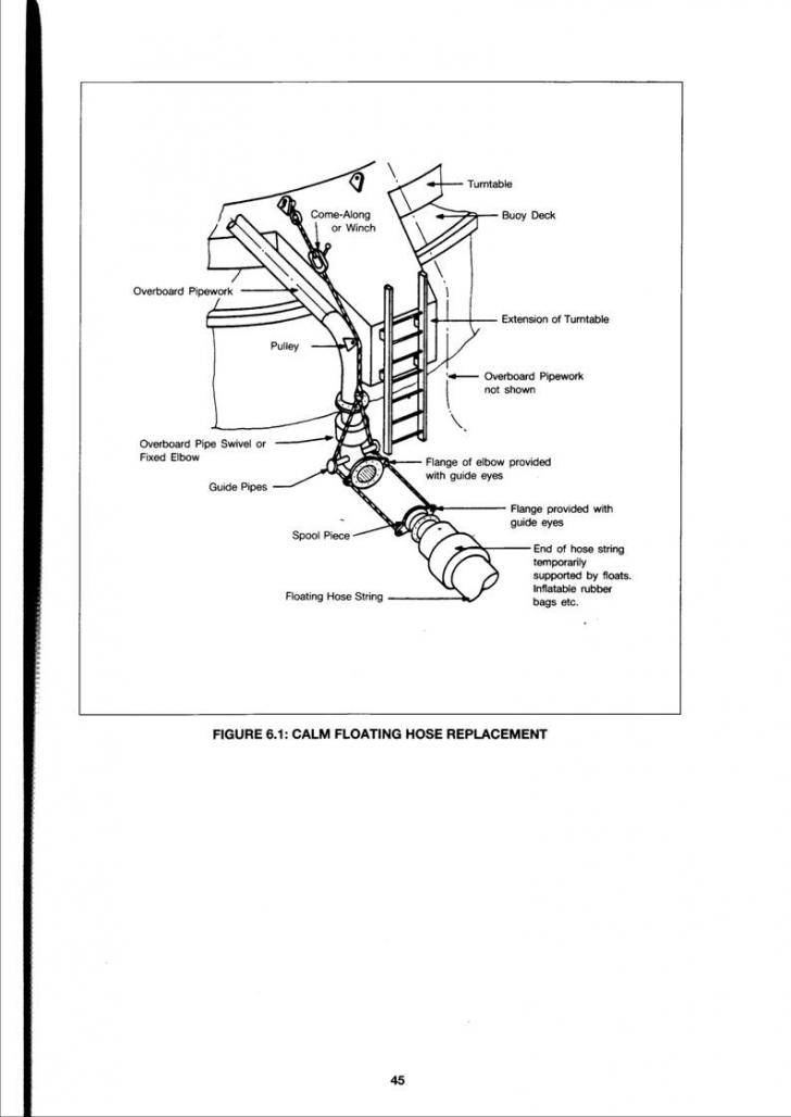
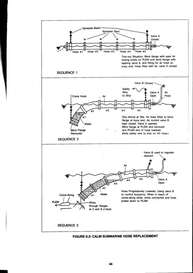
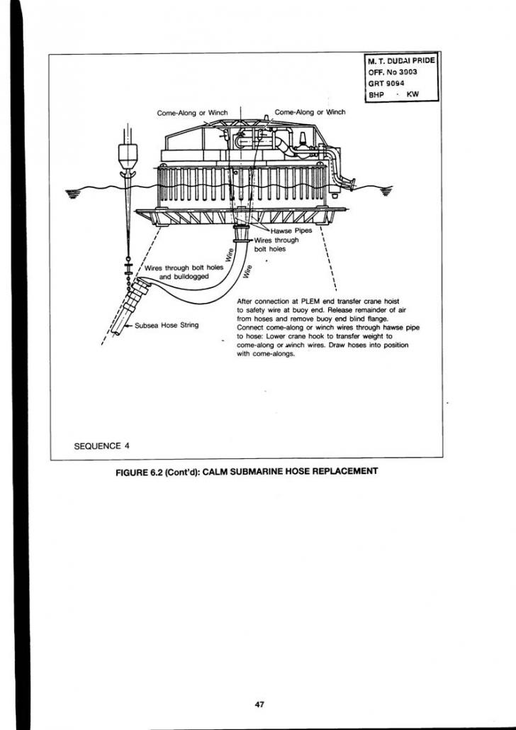
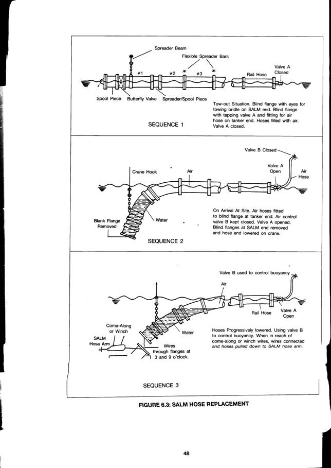
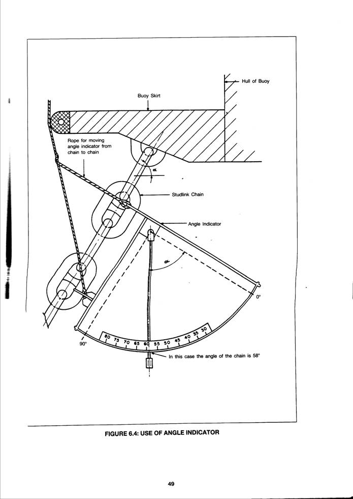
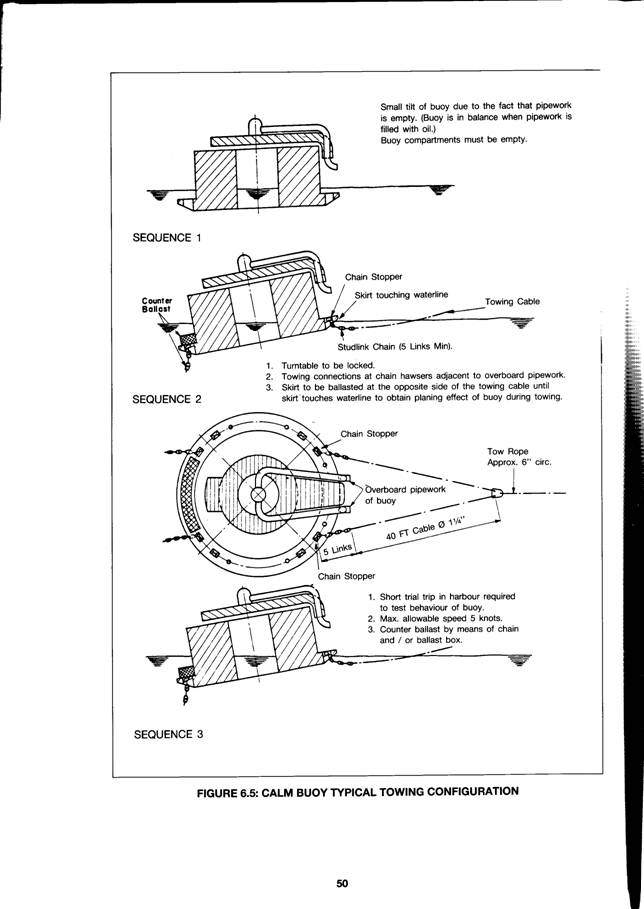
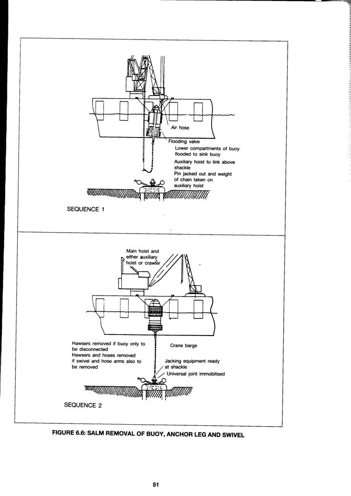
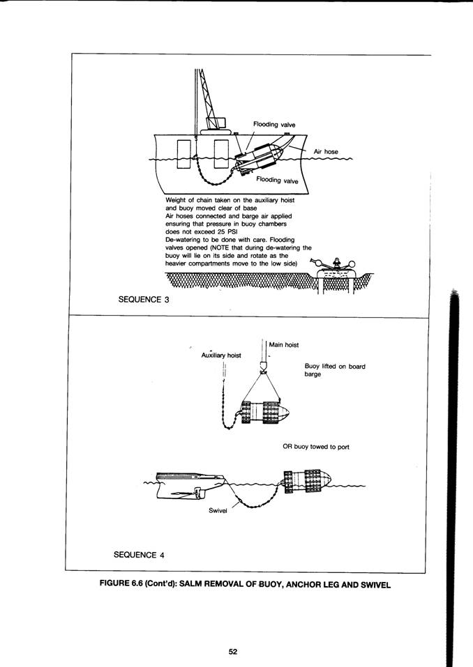
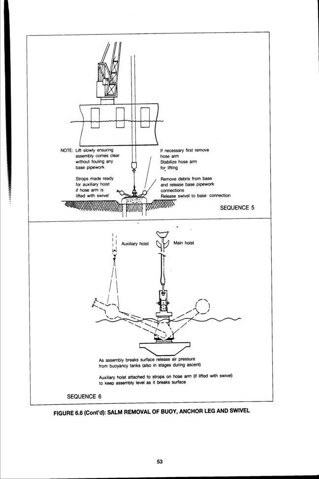
Section 7. 0
Diving and ROV Services
It is the responsibility of the owner or operator of an SPM to ensure that all underwater intervention operations carried out by divers or remotely operated vehicles (ROV) are undertaken in accordance with relevant legislation, standards and guidelines and in such a way as to ensure that persons involved are not exposed to risks to their health and safety.
At all times the integrity of the facilities should be maintained and proper regard paid to conservation of the environment.
The purpose of this chapter is to give guidance on the fundamental principles of the management of underwater intervention operations, an outline of the methods of intervention which may be employed, and the issues to be considered in selecting the most appropriate method for the particular requirement and conditions.
7.1 FUNDAMENTAL‑ PRINCIPLES
Minimise the Need for Underwater Intervention
Carrying out work underwater is in all respects the most disadvantageous option, and every effort should be made to design out the need for it. This may be achieved in a variety of simple ways, e.g., by placing, wherever possible, a component which may need periodic maintenance or repair clear of the water on the SPM, or installing surface‑controlled hydraulically‑operated valves in place of manually operated valves underwater.
Minimise Exposure to Hyperbaric Pressure
Manned diving in a hyperbaric environment involves a unique combination of occupational health and safety issues that requires effective management and control at all levels. the use of remot6 intervention technology will negate those issues. As a matter of principle manned diving should only be used where no other method is practicable and cost‑effective.
Contract all Underwater Work as a Service
It is the responsibility of the diving or ROV services contractor to undertake the work as specified in the contract safely and effectively, in accordance with Local and National Regulations. Where Local Regulations are either not in place, or are considered to be insufficiently stringent, the SPM owner or operator should specify regulations and standards with which the contractor is required to comply. The contract should specify, amongst others:
The scope of the work to be undertaken;
The operational and environmental conditions in which the work will be undertaken, including the presence in the vicinity ofthe SPM of any substances hazardous to health;
Particular requirements for equipment and tooling, e.g. surface supplied diving equipment, ROVs, underwater cleaning and inspection equipment etc.
Particular regulations and standards which are required to be complied with;
Local safety requirements, e.g., no fishing in the vicinity of the SPM.
Selection of Contractors
Contractors should be selected on the basis of their technical capability, record of safety in underwater operations and having in place appropriate rules and procedures, including emergency procedures and safety management systems.
Inspection and Audit
Personnel, equipment, certification procedures and controls should be inspected and audited against the requirements of the contract prior to commencement of the work. Additionally the proper functioning of critical systems should be demonstrated and emergency procedures exercised.
Controls
In order to ensure that all systems and local conditions are safe for the method of underwater intervention being employed, permit to work‑ procedures should be enforced.
7.2 ENVIRONMENTAL SAFETY CONSIDERATIONS
Surface wave motions and underwater currents and tidal streams imparted to the SPM can make it difficult for either a diver or ROV to carry out work on, any part of an SPM and it's associated mooring and riser systems.
When manned diving is employed the effect of SPM or diving support vessel motion should be taken into account when determining whether conditions are suitable for diving operations to be carried out.
Surface Visibility
In conditions of poor surface visibility, in addition to recognised navigational hazards, account must also be taken of the ability of a surface rescue vessel to locate and recover a diver who may surface in an emergency and be swept away from the SPM. Diving operations should be suspended if environmental conditions make this a possibility.
7.3 OPERATIONAL SAFETY CONSIDERATIONS
Over‑side Loads and Working
Materials and equipment must never be handled over the side while divers are in the water. Where this is unavoidable, e.g., it is required in support of the diving operation, all materials and equipment should be handled clear of the diver's position and secured against being dropped before being passed over the side.
Objects dropped into the water close to a diving operation create a serious risk to divers.
Surface Vessel Movements
Whenever diving operations are in progress surface vessel movements in the vicinity of the SPM are to
be strictly controlled, and no vessel is to go alongside either the SPM or the diving support vessel, without prior approval or permission of the person controlling the diving operation.
Diving on Internally Pressurised Pipelines
Divers should not be permitted to dive on pipe‑lines which are undergoing an internal pneumatic test. When a pipeline is suspected of being damaged or defective, divers should not approach to within 100 metres of the line until it's internal pressure has been reduced to less than 80% of the highest pressure to which it has been subjected since the defect was first suspected or discovered.
Fishing from SPMs
Fishing should not be permitted from or in the vicinity of an SPA
7 4 MANNED DIVING SAFETY CONSIDERATIONS
Pressure Related Illnesses
Decompression sickness is the most widely‑known form of pressure‑related illness. Other pressurerelated illnesses can occur at shallow depths as the gas in ihe body undergoes a significant change in volume over a lesser variation in depth. In such cases it is imperative that treatment should be given with the minimum of delay. In order to do this the diving contractor should have in place arrangements whereby divers can be transferred safely to a recompression chamber for therapeutic treatment.
Provisions for Treatment of Pressure Related Illnesses
When diving for whole or part of the work is at depths greater than 10 metres it is recommended that a two‑compartment recompression chamber should be available 6n site. When all diving is shallower than 10 metres a recompression chamber should be available within a maximum of 2 hours travelling time from the work site. In the latter case, if the recompression chamber is not owned by the diving contractor he must have in place a firm arrangement with the owner for it's use in an emergency.
Diver Entering and Leaving the Water
A safe method of entering and leaving the water is to be available to the diver, including a method of recovering an incapacitated or unconscious diver. In some circumstances this may require the provision of a diver‑deployment basket, in which case separate provision is to be made for the stand‑by diver and there is to be both a primary and secondary method of recovering each basket.
Head Protection
In order to protect the divers' head from impact with any part of the SPM system due to relative motion, some form of head protection is required. This is best provided by using hard helmets.
Use of Closed‑Circuit.Television (CCTV)
A head‑mounted CCTV camera with surface monitor, where available, can provide useful information to both the diving supervisor and the SPM owner.
High Pressure Water. Jetting Equipment
This equipment can emit high levels of noise, and when divers are required to use it then ear‑protection is required.
7.5 USE OF HYPERBARIC DIVING SERVICES
Surface Oriented Diving
The nature of their service usually implies that SPMs will be located in water depths shallower than 50 metres. At these depths and for the routine type of work required on SPMs surface‑oriented diving may be used. Therefore this method of manned diving only is addressed. In deeper water, or when there is an intensive programme of heavy construction, repair or abandonment work , to be undertaken, saturation diving may be required, and specialist assistance should be sought.
Self Contained Underwater Breathing Apparatus (SCUBA)
This equipment generally lacks three elements which are considered to be essential to the safe conduct of commercial diving:
Renewable supply of breathing gas. The amount of gas used by a diver depends on the depth at which he is working and his work‑rate. Divers frequently fail to monitor their own gas usage, and any one of them may find, himself with only his emergency supply left and unable to s4ff#pe safely in ‑a controlled manner.
Depth monitoring. It is imperative that thi diving supervisor knows the maximum depth at which a dive has taken place, and to be able to control the depth of a diver during decompression in the water. It can also be a working guide in demonstrating that the diver is at the correct depth for a mid‑water work site.
Voice communications. This is an indispensable tool for the diving supervisor. It enables him to monitor the safety of the diver by listening to his breathing pattern and hearing any sounds of distress or calls for help. It also enables him to give precise work instructions to the diver, and, to answer any queries the diver may have regarding the work.
SCUBA may be used for commercial diving operations:
When the diving services contractor can demonstrate in writing that, it's use ‑under specific circumstances would be safer than using surface‑supplied equipment.
In water depths shallower than 10 metres.
For light work, e.g. observation and visual survey.
Surface Supplied Breathing Apparatus (SSBA)
This is considered to be the safest method for commercial diving because it permits all aspects of the dive to be monitored and controlled at the surface by the diving supervisor, including renewal of the divers' supply of breathing gas.
It comprises a surface control panel for supplying breathing gas, a hard‑line communications link and depth measuring system, all linked to the diver via an umbilical. The divers' personal equipment includes an emergency supply of breathing gas.
Light‑Weight SSBA
SSBA is often considered to be too cumbersome for use on an SPM, particularly for jobs of a short duration. However it is possible for the diving services contractor to assemble a compact version b% making‑up a small portable control panel, and utilising approved breathing gas storage cylinders to supply the required amount of breathing gas for the job. The breathing gas supply system should be arranged so that a reserve gas supply is always available on‑line to the diver except, when the main supply is exhausted and the reserve put in use, the empty cylinder may be temporarily removed to be
replaced by a full one. The size and number of cylinders required would depend upon the water depth, duration of the dive and whether the work is heavy or light.
Such systems should continue to meet the basic requirements of surface monitoring of the gas supply and divers' depth, and a voice communications link.
Use of NitrogenlOxygen (Nitrox) Breathing Gas
Air is the most commonly‑used breathing gas for divers at depths down to 50 metres. However in the 30‑50 metre depth range it requires a significant amount of time to decompress a diver such that the time required to decompress can be much greater than the time spent working. It can also cause nitrogen narcosis in some divers, impairing their ability to work safely and effectively. A way of mitigating these effects is to use a nitrox mix where the level of oxygen is greater than in air. The concomitant reduction in the level of nitrogen reduces the time required for decompression, and reduces the possibility of nitrogen narcosis occurring.
There are, however, attendant risks associated with the use of nitrox. The partial pressure of the oxygen must never be permitted to exceed 1.5 bar, otherwise the diver may suffer oxygen toxicity. At the best this may lead to temporary lung impairment, it may result in the diver suffering convulsions, and at worst it can be fatal.
The diving services contractor must be experienced in the use of nitrox as a breathing gas, as must all of the diving supervisors and the divers. The contractor will advise the SPM owner or operator on the implications of using this technique, and will determine the safe level of oxygen for a nitrox mix according to the maximum working depth of a dive.
Diving Team Size
The absolute minimum number of people required in a diving team is three: a diver, stand‑by diver and supervisor. However this will only permit two consecutive no‑decompression dives in shallow water and only one dive, limited in duration by the decompression requirements, at deeper depths. Additional team members will be required to operate plant and equipment, and dive for more extensive operations.
Diver Competency
All divers should have undergone theoretical and practical training in commercial diving, including the operation and maintenance of all types of plant and equipment to be used and the application of routine and therapeutic decompression procedures. They should also be certified as being medically fit to undertake commercial diving. Diving supervisors should be qualified commercial divers experienced and knowledgeable in all aspects of diving and the work which is to be undertaken. Preferably they should have attended a formal training course for commercial diving supervisors.
7.6 USE OF REMOTELY OPERATED VEHICLES (ROV)
R 0 V Capabilities
ROVs come in a range of types and capabilities, and are capable of carrying out all inspection work associated with SPMs and, given the appropriate level of pre‑engineering, a significant range of maintenance and repair tasks. The effectiveness of ROVs in respect of both their operation and cost is dependent upon proper planning of the work and provision of the appropriate tooling to ensure their access to and interfacing with the various components of the SPM.
Would‑be users of ROV services should be aware that no ROV can match the dexterity, flexibility and tactile senses of a human‑being doing the work directly, and consequently an ROV will usually take longer than a diver to complete many underwater tasks. However a survey of their availability at the
required location and analysis of the cost benefits to be realised should be carried out before committing to this method.
Types of ROV
The following sections provide a brief description of the three main groupings of ROV in order to roughly quantify the equipment inventory and space requirements of each. With over three hundred different models available world‑wide it will be appreciate that this can only be a very broad‑brush guide.
Low Cost ROV(LCROV)
These are generally compact systems which may be hand‑carried, although when deployed in deep waters a simple handling system such as a powered block will be required. The vehicle fits within an envelope of about 0.5m x 0.5m x 0.5m, typically
weighs <60kg and requires two people to deploy and operate. Being light‑weight and low‑powered they are not capable of use
in >Sea State 4 or tidal streams A.5 knots.
They are fitted with a single camera and are mainly used for general visual surveys and monitoring divers.
Observation Vehicles
These vehicles can be used safely in wave conditions up to about sea‑state 6, and can operate effectively in tidal streams up to about 0.75 knots. Their power, video quality, and ability to mount additional stills cameras or light‑weight sensors enable them to be used for light inspection tasks as well as for diver monitoring and support. Excluding any tooling packages which may be mounted on an ROV, the basic components of a total ROV system which need to be taken into account when planning the mobilisation of a system are:
Typical system component dimensions and weight (in air):
ROV ‑ 1.0metre x 0.6metre x 0.6metre < 90kg
Tether Management System (TMS) ‑ 1.0metre x 1.0metre, 0.5tons
Deployment skid ‑ 3.5metres x 2.Ometres, 6.Otons
Control cabin ‑ 5.Ometres x 2.4metres, 10.Otons
Workshop ‑ 3.Ometres x 2.4metres, 7.Otons
Work Class Vehicles
These are the larger types of vehicle which, with good planning and engineering, are capable of undertaking the majority of tasks performed by divers using either sophisticated manipulators or purpose‑built tooling packages. However for work on facilities which were not specifically designed to facilitate ROV intervention it may be necessary either to develop special engineering procedures for specific tasks, or replace those components which are required to be maintained or changed‑out b% ROV. These vehicles can be used safely in wave conditions up to about sea‑state 7, subject to suitable launch platform, and can operate comfortably in tidal streams of up to about 1.0 knots. Specifications for system components for the different types of vehicle in this class can vary significantly at either end of the scale, but are typically:
Typical system component dimensions and weight (In Air):
ROV ‑ 2.0‑2.5metres x 1.0metre x 1.5 metre, 0.5 tons ‑ 2.0 tons
TMS ‑ 2.0 metres x 2.0 metres 2.0 tons
Deployment Skid ‑ 8.0 metres x 3.0 metres, 30.0 tons
Control Cabin ‑ 6.1 metres x 2.4 metres, 12.0 tons
Workshop ‑ 6.1 metres x 2.4 metres, 15.0 tons
Charge Cart ‑ 2.4 metres x 2.4 metres, 2.0 tons
Section 8. 0
Support Facilities
This section provides a general overview of the supporting craft and shore facilities required for operation, maintenance and repair of SPMs. The design of support craft and shore facilities largely depends on the phYsical needs of each individual terminal coupled with weather, environmental and regulatory considerations.
8.1 CRAFT FOR MARINE OPERATIONS
Mooring Launches
There is no standard specification for a mooring launch since the specific conditions at the offshore location will dictate operational and technical requirements. Sea conditions, weather and distance from shore are prime determining factors.
The design and location of the superstructure should be such that it is placed well forward to provide good visibility, a large clear deck area and should be set inboard to prevent contact with the tanker's side while alongside.
The deck configuration should make allowances for bitt spacing for pick‑up hoses, freeboard to permit safe pick‑up of hoses and ropes, towing bitt or hook, capstans to assist with hose pick‑up, openings to safely embark and disembark personnel, and a stowed or recessed anchor.
In addition, the following factors should be considered when selecting a mooring launch for a particular site:
Weather and sea state for normal operations.
Port facilities available.
Distance from shore facilities.
Time on station.
Mooring and hose connection equipment to be carried.
Lighting (deck/overside).
Pollution equipment.
Visibility from wheelhouse.
Fendering to permit hawser and hose pick‑up without snagging.
Back‑up hydraulic units for valve actuation.
Fuel and water capacity.
Facilities for pumping bilge water to shore.
Exhaust system to ensure there is no ignition hazard.
Local conditions will dictate hull dimensions. Mooring launches are typically between 13 and 26 metres in length and 3.5 and 8.0 metres in beam. The horsepower required also depends on the overall duties of the launch. Most launches, however, fall in the 2 x 200 HP to 2 x 400 HP range. Other factors such as towing capability and maintenance requirements will also play a part in final horsepower determination. Consideration should be given to the water cooling system if problems from fouling by ropes, dirt~ water and marine growth, etc., are to be avoided.
The total quantity of items carried on board the launch for mooring and hose handling purposes should be sufficient to cover the equipment listed in section 4.1.1.
Maintenance Vessels
Terminals with only one SPM can usually perform the required maintenance with a modified supply or tug boat. Terminals with more than SPM normally need a specially‑built vessel to cope with the maintenance workload. A maintenance vessel should be capable of performing the following tasks:
Diving support.
Mooring hawser change out.
Floating/submarine hose change‑out.
Hose storage/handling.
Fire‑fighting.
Maintenance of navigational aids.
Hydraulic valve operation.
Pressure testing of hose strings.
Repair of SPM system components.
Removal of marine growth.
Oil spill clean‑up.
The following facilities should be considered for the maintenance vessel:
Diving equipment.
Service air compressors.
Tugger winches.
Four‑point mooring capability.
Crane with 40 tons lifting capacity over the working deck and a minimum jib height equal
to a standard single hose length plus approx. 3 metres.
Drain trough for oily water from hose flanges.
Slop tank with capacity equal to hose string volume plus 50%.
Oil water separator.
Beam equal to standard single hose length plus approximately 3m.
Adequate hose securing points on deck.
Hydraulic and air impact wrenches.
Water jetting equipment if marine growth is a problem.
Welding and burning equipment.
Oil spill clean‑up equipment.
Adequate water‑purging pumps, capable of flushing the hose system.
Small workshop for repairing system hardware.
Stern steering station enclosed in wheelhouse with upward vision.
Sufficient accommodation to meet all maintenance personnel needs.
Heavy maintenance work, such as lifting the SPM buoy out of the water, usually requires the use of ~pecial vessels or barge with heavy lift capability. A maintenance vessel designed specifically for SPM work will normally include facilities for the complete disconnection of CALM or SALM buoys for towing ashore if the location allows. Heavy lift equipment is usually required to replace chain anchor legs, to remove SALM swivels and PLEM assemblies.
Z~
Major repair an& maintenance is normally carried out within a weather window and it is therefore, essential that the maintenance vessel has the facilities to support personnel engaged in shift work.
Use of Tugs in Operational Support
Tug assistance may be'required at a SPM to maintain a taut mooring, for example when yawing is a problem or at a tide change. In such cases, a tug or mooring launch of sufficient size and horsepower should be used.
8.2 SHORE MAINTENANCE FACILITIES
The extent to which dedicated onshore maintenance facilities are required will be determined by necessity. Determining factors include:
Location.
Availability of other facilities within the area with necessary equipment and skilled personnel.
Port throughput.
Number of SPMs.
Berth occupancy.
Frequency of hose string change‑outs.
8.2.1 Yard and Storage Facilities
The following onshore facilities are required to support an SPM operation. The degree of sophistication largely depends on the number of SPMs operated and the time available to perform maintenance tasks.
Storage of SPM Spares
Warehouse storage of spare parts is recommended. Warehouse storage of some spares is necessary since open stowing in severe weather conditions can cause rapid degradation of some components such as mooring hawsers, seats, rubber expansion joints, rubber hoses, synthetic chain support buoys and pick‑up buoys. A sufficient number of spares should be stored at the shore yard to ensure uninterrupted operation of the SPMs. The quantity of spare parts required will depend on the service life and delivery lead time of each replacement part.
Hose Testing, Repair and Storage
Hoses should be tested, inspected and stored in accordance with the OCIMF publication entitled 'Guidelines for the Handling, Storage and Inspection of Hoses in the Field'.
Facilities for Major Overhaul
The SPM operator should own or have access to a crane capable of lifting the SPM buoy out of the water for a major overhaul, or have access to dry‑dock facilities. In addition, a barge or sufficient dock space is required on which to place the SPM buoy while it is being overhauled. A covered work area is desirable when repairing a product swivel or turntable.
Dock Space for Service Vessels
When mooring launches and maintenance vessels are owned or long‑term leased, consideration should be given to providing permanent dock space for use when the craft are off‑station. Dock services to be considered should include water, fuel, electrical power and a slop tank for pumping bilges
Section 9.0
Spare Parts
A sufficient quantity of spare parts should be available to ensure reliable uninterrupted operation of the SPNI.
The following recommendations for the quantities of spare parts to be kept in stock are based on A facility consisting of a single SPM. If the facility consists of more than one SPM a full spares back‑up will not be required for each SPM.
Many of the items listed have been generalised due to the different types and manufacturers of SPMs.
Except where limited shelf life dictates otherwise, more than 100% back up may be required when both lead times and usage are taken into account.
9.1 SPARE PARTS APPLICABLE TO ALL SYSTEMS
Submarine and Floating Hose System
Hose couplings, spreaders, spool pieces and gaskets 100%
Hoses, both submarine and floating 100%
Buoyancy tanks or floats 100%
Tanker rail hoses and first off the buoy hoses 200%
Valves and flanges 20%
Lifting chains, shackles, etc. 200%
Hose lights, battery packs, etc. 100%
Associated bolts 200%
Pick‑up buoys 200%
Mooring Assemblies
Mooring hawsers 200%
Chain support, buoy shackles, pins, thimbles and lifiks 100%
Triangular plate 100%
Chafing chain 200%
Hawser floats 100%
Messenger lines 200%
Marker buoys 100%
PLEM
Valves 50%
Associated bolts and gaskets 200%
Purge fittings 100%
Control system As necessary
Spool pieces 50%
Anodes 50%
9.2 SPARE PARTS APPLICABLE TO CALM SYSTEMS ONLY
Buoy Body and Turntable
Chain stoppers 50%
Manhole cover seals 100%
Bogey wheels (for CALMs with bogey wheels only) 50%
Expansion joints 100%
Main bearing seals 100%
Fluid swivel bearing seals 100%
Bearing bolts 100%
Navigational lights complete 100%
Lamps 400%
Batteries for navigation lights 100%
Associated bolts 200%
Anodes 50%
Valves and flanges 50%
Anchor Chain System
Shackles and chain links 20%
Anchors 20%
9.3 SPARE PARTS APPLICABLE TO SALM SYSTEMS ONLY
Buoy Body
Manhole cover seals 100%
Flooding valves 50%
Fender equipment 50%
Navigational lights complete 100%
Lamps 100%
Batteries for navigation lights 100%
Associated bolts 200%
Anodes 50%
Anchor Leg
Chain Swivel 100%
Main Swivel and Hose Arm Assembly
Main Swivel Seals 100%
Associated bolts 200%
Anodes 50%
Spool pieces 50%
Section 10. 0
Records
The schedules necessary for regular maintenance, servicing and replacement of the components of a SPM can only be established with experience. The condition of individual components will depend upon specific design parameters, operating history and environmental factors and will differ for each SPM. A major requirement therefore is that detailed records are kept of each item of equipment in service or in spare stock.
10.1 RECORD CONTENT
Records should include:
Basic data of dimensions and strength.
Dates received, dates in service and reason for retirement.
The exact location of the item of equipment within the system.
Details of wear observed during inspections.
Details of subsequent tests, maintenance or repairs.
Such records will be of invaluable assistance and are essential for ensuring efficient maintenance.
Observations made, and records kept, during the early months of operating a new SPM are of particular importance as these will give the first and earliest indication of the deterioration to be expected, particularly for components which require more frequent replacement. Moreover, these early observations will enable the terminal operator to revise, if necessary, the inspection and maintenance schedules outlined in Sections 5 and 6.
Individual components of the SPM should be covered by records to a degree that will ensure they receive sufficient attention as required by their function if the system and the degree of wear observed. In this way, the risk of breakdown and unscheduled repair work will be substantially reduced. The amount of records kept will depend on the service requirements and design of the SPM and its operating procedures. Some typical areas which should be covered are described in Section 10.2 Specimen record sheets are given at the end of this section and these may prove to be useful for reference purposes.
10.2 TYPICAL AREAS TO BE COVERED BY THE RECORD SYSTEM
Pre and Post Mooring Checks
Each time a vessel berths at a SPM a general inspection should be made of all equipment and materials which are within easy reach at that time. Any small defects should be made good at the earliest opportunity so as to prevent further deterioration. A check list should be completed by the berthing master both before and after berthing. A sample of 'Pre and Post Berthing Check List' is given in Figure 10.1.
Operating Mooring Data
The relevant sections of the 'Operating Mooring Data' sheet should be filled in every hour a ship is on the mooring, and if possible every four hours at other times. In weather conditions that are changing rapidly, the frequency of observations should be increased so that a re‑construction of the broad pattern can be carried‑ out from the recorded data.
In cases where instruments are not available for recording certain weather criteria, best estimates should be made and the letter 'E' inserted after the observation to draw attention to the fact that it was estimated.
The information contained in the data sheets is useful for relating failures back to specific exceptional conditions. It also enables operating staff to prepare for similar circumstances in the future. A sample of an 'Operating Mooring Data Sheet' is given
in Figure 10.2.
Equipment Performance
As stated previously, each item of equipment should be covered by the record system so that its condition can be monitored and any rapid deterioration quickly identified. Moreover, inspection and maintenance schedules can be modified, as necessary, in the light of the experience gained.
Major items for which specimen record or performance sheets are given are as follows, and samples of record sheets are given in Figures 10.3 to 10.6.
Mooring Hawsers:
To record the operating history and performance of mooring ropes based on the number and duration of berthing.
Other mooring assembly components such as chafing chains, triangular plates, chains and shackles:
Similar to those for mooring hawsers.
Anchor Chains:
To record periodically the position of the chain stoppers and the angle of pretension on the chain pendants. These recordings should be made at regular intervals and during any chain adjustment operation. It is recommended that the measurement of the angle of pretension should be repeated to reduce errors. The average observation should be compared with the prescribed angle of pretension. It is recommended that these measurements be only made during slack tide. (CALM only)
Anchors:
To record the position of the anchors, the distance between the anchor crown and marker peg is measured. The records will show whether any drag of the anchors has occurred over a period of time. Any embedding, scouring, etc., should be noted for each anchor (CALM only).
Submarine and floating hoses:
Specimen sheets for the Hose Performance Card are given in the OCIMF publication. 'Guidelines for the Handling, Storage, Inspection and Testing of Hoses in the Field' ‑ latest edition.
10.2.4 Overall SPM Performance
In addition to the records for individual components, records of berth occupancy, throughput and downtime will, if maintained over a period of time, give a valuable indication of overall terminal performance. The required data should be entered every day. Monthly and yearly cumulative figures expressed as total times and percentages will indicate performance and utilisation trends. A sample of an 'Overall SPM Performance Data Sheet' is given in Figure 10.7
|
SPM RECORD SHEET |
BERTH INSPECTION DATA |
||||
|
SPM LOCATION |
DATE: |
||||
|
PRE BERTH CHECK SPM CHECK: POST DEPARTURE CHECX- SATISFACTORY SATISFACTORY |
|||||
|
YES |
NO |
TRIM & FREEBOARD |
YES |
NO |
|
|
YES |
NO |
MOORING CONNECTIONS |
YES |
NO |
|
|
YES |
NO |
OBSERVED DAMAGE |
YES |
NO |
|
|
YES |
NO |
HOSE CONNECTIONS |
YES |
NO |
|
|
YES |
NO |
PIPEWORK |
YES |
NO |
|
|
YES |
NO |
SWIVELS |
YES |
NO |
|
|
YES |
NO |
VALVES |
YES |
NO |
|
|
YES |
NO |
BEARINGS |
YES |
NO |
|
|
YES |
NO |
INSTEWMENTS |
YES |
NO |
|
|
YES |
NO |
SYSTEM PRESSURISED |
YES |
NO |
|
|
YES |
NO |
HATCH SECURITY |
YES |
NO |
|
|
YES |
NO |
RUBBER EXPANSION PIECES |
YES |
NO |
|
|
YES |
NO |
PRESSURE GAUGES |
YES |
NO |
|
|
YES |
NO |
NAVIGATION EQUILPMENT |
YES |
NO |
|
|
YES |
NO |
LIGHTING SYSTEMS |
YES |
NO |
|
|
ACTION REQUIRED: |
|||||
|
PRE BERTH CHECK: SPM CHECK: POST DEPARTURE CHECK: SATISFACTORY SATISFACTORY |
|||||
|
YES |
NO |
HAWSER ASSEMBLY |
YES |
NO |
|
|
YES |
NO |
CHAFING CRAM |
YES |
NO |
|
|
YES |
NO |
SUPPORT BUOYS |
YES |
NO |
|
|
YES |
NO |
SHACKLES |
YES |
NO |
|
|
YES |
NO |
PICK-UP ROPE |
YES |
NO |
|
|
YES |
NO |
FLOATING HOSES |
YES |
NO |
|
|
YES |
NO |
RAILHOSES |
YES |
NO |
|
|
YES |
NO |
PICK-UP GEAR |
YES |
NO |
|
|
YES |
NO |
VALVES |
YES |
NO |
|
|
YES |
NO |
GEAR BASKET |
YES |
NO |
|
|
YES |
NO |
REDUCERS |
YES |
NO |
|
|
YES |
NO |
HOSE LIGHTS |
YES |
NO |
|
|
YES |
NO |
FLOATING Y-PIECE |
YES |
NO |
|
|
ACTIONREQUIRED: |
|||||
FIGURE 10.1: PRE AND POST BERTHING CHECK LIST
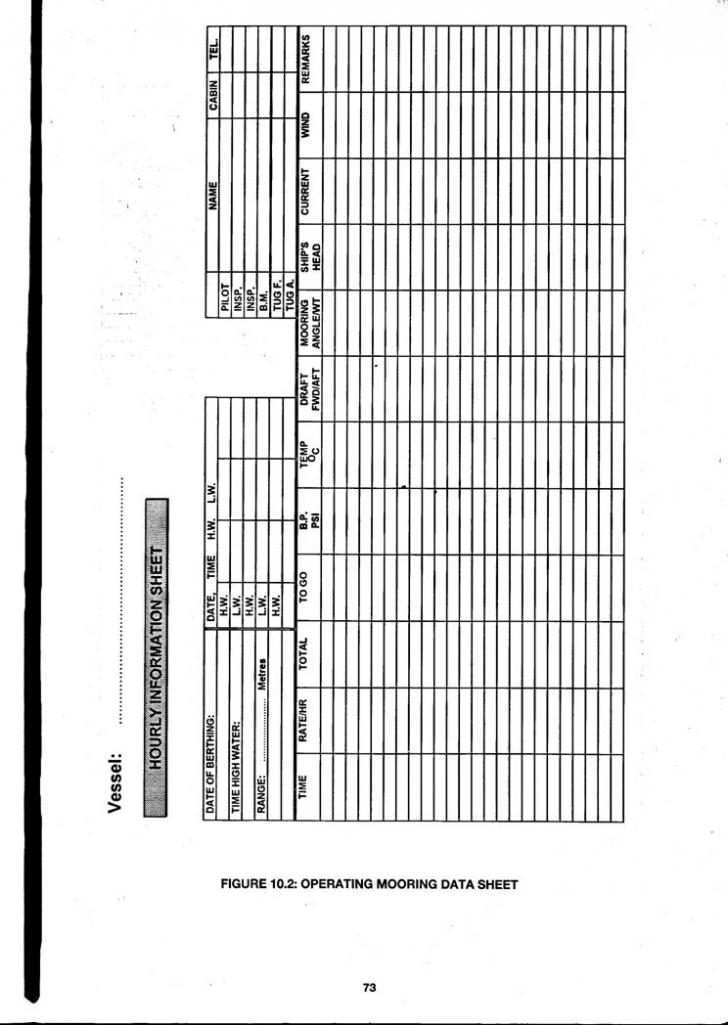
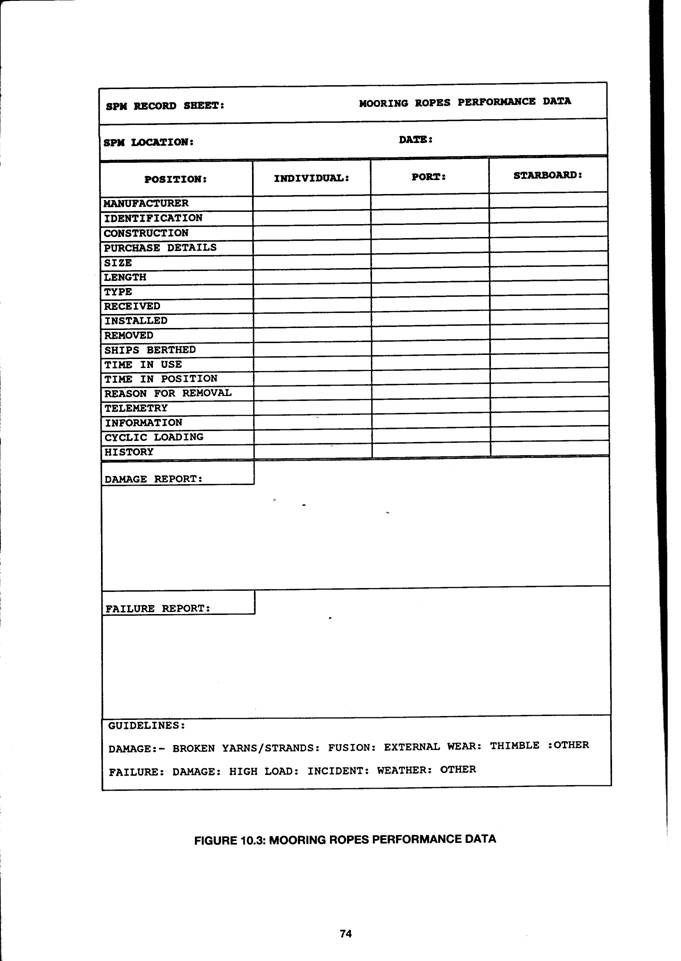
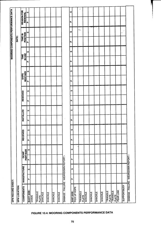


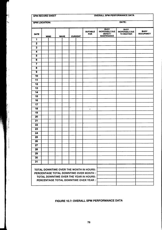
|
Politica de confidentialitate | Termeni si conditii de utilizare |

Vizualizari: 19162
Importanta: ![]()
Termeni si conditii de utilizare | Contact
© SCRIGROUP 2025 . All rights reserved