| CATEGORII DOCUMENTE |
| Bulgara | Ceha slovaca | Croata | Engleza | Estona | Finlandeza | Franceza |
| Germana | Italiana | Letona | Lituaniana | Maghiara | Olandeza | Poloneza |
| Sarba | Slovena | Spaniola | Suedeza | Turca | Ucraineana |
1 Theoretical Background
1.1 Basic Theory of Axial Deformation
Definition 1
A plane linear member, when subjected to exterior loads and/or change of temperature, undergoes an axial deformation if after the deformation:
(a) the axis of the member remains straight;
(b) the cross-sections remain plane, perpendicular to the longitudinal axis of the beam and do not rotate about the same longitudinal axis after the deformation.
Equilibrium Equation

Figure 1 Equilibrium of an Elementary Beam Volume
The differential relation between the exterior load and the axial internal resultant is obtained from the equilibrium of the elementary volume:
![]() (1)
(1)
where ![]() is the distributed
loading parallel to the beam longitudinal axis and
is the distributed
loading parallel to the beam longitudinal axis and ![]() is the axial stress
resultant .
is the axial stress
resultant .
Integrating equation (1) the stress resultant force ![]() in a particular
cross-section is calculated as:
in a particular
cross-section is calculated as:
![]() (2)
(2)
where ![]() is the value of the axial force at the origin of the
integration interval.
is the value of the axial force at the origin of the
integration interval.
Strain-Displacement Equation
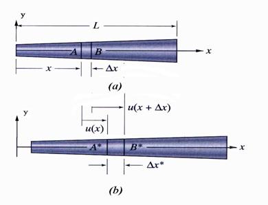
Figure 1 Geometrical Aspects of the Axial Deformation
(a) Undeformed Member and (b) Deformed Member
The extensional
strain ![]() along the longitudinal
axis of the beam is obtained using the notation shown in Figure 1:
along the longitudinal
axis of the beam is obtained using the notation shown in Figure 1:
![]() (3)
(3)
The rest of the generalized strain tensor components, extensional and shear strains, are:
![]() (4)
(4)
![]() (5)
(5)
![]() (6)
(6)
The expression of the generalized strain tensor ![]() is:
is:
 (7)
(7)
The displacement ![]() is obtained by integration the differential equation (3):
is obtained by integration the differential equation (3):
![]() (8)
(8)
where ![]() is the displacement at the beginning at the integration
interval.
is the displacement at the beginning at the integration
interval.
The elongation is calculated using equation (8) as:
![]() (9)
(9)
where ![]() is the total length of the bar.
is the total length of the bar.
Constitutive Equation
The constitutive equation reflects the relation between the
stress and the strain. If the linear elastic
material behavior is considered, applying the Hooks Law, the relation
between the normal stress ![]() and extension strain
and extension strain ![]() is written:
is written:
![]() (10)
(10)
where![]() is the modulus of elasticity and is obtained performing
tensile tests.
is the modulus of elasticity and is obtained performing
tensile tests.
Considering the assumption that the cross-section of the bar
is a small surface, the variation of the modulus of elasticity ![]() is negligible on this surface, and consequently, the
constitutive equation (10) is expressed as:
is negligible on this surface, and consequently, the
constitutive equation (10) is expressed as:
![]() (11)
(11)
Note: equation (11) implies that the normal stress ![]() varies only along the
length of the member, but has a constant value on the entire cross-section.
varies only along the
length of the member, but has a constant value on the entire cross-section.
The representation of the normal stress ![]() is shown in Figure 2.
is shown in Figure 2.
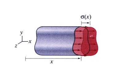
Figure 2 Cross-Section
Note: equation (11) implies that the normal stress ![]() varies only along the
length of the member, but has a constant value on the entire cross-section.
varies only along the
length of the member, but has a constant value on the entire cross-section.
The rest of the stress tensor ![]() components are zero:
components are zero:
![]() (12)
(12)
![]() (13)
(13)
Consequently, the generalized stress tensor is:
 (14)
(14)
Cross-Section Stress (Internal) Resultants
The following cross-sectional stress (internal) resultants are obtained using the stress distribution expressed by equation (11) through (13):
![]() (15)
(15)
![]() (16)
(16)
![]() (17)
(17)
The relations between the normal stress ![]() and the cross-section
resultants
and the cross-section
resultants![]() ,
, ![]() and
and ![]() are derived using the
notation shown in Figure 3.
are derived using the
notation shown in Figure 3.
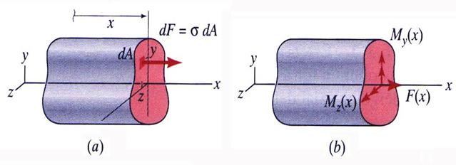
Figure 3
(a) Normal Stress and (b) Stress Resultants
If the axes ![]() and
and ![]() of the coordinate system intersect such that the
of the coordinate system intersect such that the ![]() axis passes through the cross-section centroid, the static
moments
axis passes through the cross-section centroid, the static
moments ![]() and
and ![]() are zero and the axial
force
are zero and the axial
force![]() remains the only non-zero stress resultant:
remains the only non-zero stress resultant:
![]() (18)
(18)
![]() (19)
(19)
![]() (20)
(20)
Then, from equation (18) the normal stress![]() is calculated as:
is calculated as:
![]() (21)
(21)
Note: It is concluded that a beam made from a linear elastic material undergoes an axial deformation if the axial force passes through the cross-section centroid.
Thermal Effects on Axial Deformation
The thermal strain was introduced as:
![]() (22)
(22)
where ![]() is the thermal
expansion coefficient and
is the thermal
expansion coefficient and ![]() is the change in the
member temperature.
is the change in the
member temperature.
The total elongation strain is the sum of the elongation strain induced by the exterior load action and thermal effects and is expressed as:
![]() (23)
(23)
Then, the total elongation of the member is written as:
![]() (24)
(24)
Uniform-Axial Deformation
Definition 2
The uniform axial-deformation element is a linear member characterized by:
(a) a constant area along the entire length of the member;
(b) is made of a homogeneous elastic material;
(c)
is subjected to a constant axial force ![]()
Uniform-axial deformed members (shown in Figure 4)
.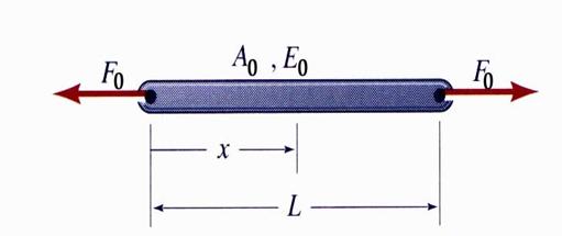
Figure 4 Member Exhibiting Uniform Axial-Deformation
Transcribing the requirements of the definition 2 the following expressions are obtained:
![]() (25)
(25)
![]() (26)
(26)
![]() (27)
(27)
Note: Equation
(27) implies the absence of the distributed load![]() .
.
Rewriting equations (21), (23) and (24) previously obtained for the case of the member with uniform axial-deformation the following equations are obtained:
![]() for axial stress (28)
for axial stress (28)
![]() for elongation strain (29)
for elongation strain (29)
 for total elongation (30)
Axial flexibility and stiffness coefficients
![]() the axial
stiffness coefficient. (31)
the axial
stiffness coefficient. (31)
![]() axial
flexibility coefficient (32)
axial
flexibility coefficient (32)
Substituting the equation (32) into the total elongation expression (30), the total elongation of a bar under uniform-axial deformation is recast as:
![]() (33)
(33)
Nonuniform-Axial Deformation
If any one of the assumptions contained in definition 2 is violated the axial deformation is called nonuniform-axial deformation. The most common cases of nonuniform-axial deformation are:
Member with non-homogeneous cross-section;
Member with variable Cross-Section;
Member loaded along its length.
The formulae described in the section 1.1 have to be adapted function of the situation.
Verification of the Members Subjected to Axial Deformation
The design formula used is the relationship between maximum
normal stress ![]() and the allowable
normal stress
and the allowable
normal stress![]() :
:
![]() (34)
(34)
The formula (34) was used for a long period of time in a
procedure known as the allowable-stress
design. Due to the simplicity of application, this method is still commonly
used in
The allowable normal stress ![]() is defined by limiting
the value of the normal stress in the axially deformed member. Dividing the
yield stress
is defined by limiting
the value of the normal stress in the axially deformed member. Dividing the
yield stress ![]() pertinent to the material subjected to axial deformation by a
safety factor
pertinent to the material subjected to axial deformation by a
safety factor![]() the allowable axial stress is calculated:
the allowable axial stress is calculated:
![]() (35)
(35)
The safety factor is greater than one, usually taking values between 2 and 3. The yield stress for different materials is found in Appendix 1.2.
2 Solved Problems
Problem 2.1
A solid brass rod AB and a solid aluminum rod BC are
connected together by a rigid coupler of negligible length at B as shown in
Figure 2.1.a. The diameters and the modulus of elasticity of the two segments
are d1 = 65 mm, d2 = 50 mm, E1 = 105 GPa and E1
= 69 GPa, respectively. The system is loaded by two concentrated loads, ![]() and
and ![]() , acting along the
centroidal line of the system at point
, acting along the
centroidal line of the system at point ![]() and
and ![]() , respectively . Calculate the axial stress existing in the
two rods and the displacement at point B and C. Verify the rod segments.
, respectively . Calculate the axial stress existing in the
two rods and the displacement at point B and C. Verify the rod segments.
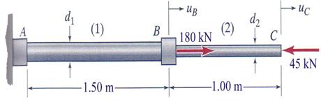
Figure 2.1.a
A. General Observations
Two axial forces are acting on the rod:
![]() and
and ![]()
The areas of the two rod segments are:

![]()
![]()

![]()
![]()
B. Calculations
B.1 Free-Body Diagram
The constraint located at point A is
replaced by a horizontal reaction ![]() as shown in Figure 2.1.b.
as shown in Figure 2.1.b.
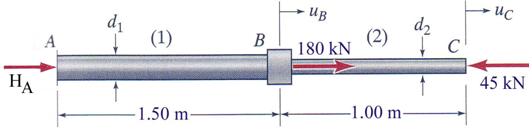
Figure 2.1.b
B.2 Reaction Calculation
The equation of equilibrium used is the projection of all
axial forces on the horizontal axis![]() :
:
![]()
![]()
![]()
The equilibrium equation contains only one unknown reaction
force,![]() , and consequently, the system is statically determinate.
, and consequently, the system is statically determinate.
B.3 The Axial Force Diagram
The axial force diagram is drawn in Figure 2.1.c.

Figure 2.1.c
The axial force on the interval ![]() is a constant tension force
is a constant tension force![]() ,
while on the interval
,
while on the interval ![]() is a constant
compression force
is a constant
compression force ![]() .
It can be concluded that both segments of the rod are uniform-axial deformed members.
.
It can be concluded that both segments of the rod are uniform-axial deformed members.
B.3 Stress and Strain Calculation
The stress and strain in the interval![]() , where the rod is made of solid brass are obtained as:
, where the rod is made of solid brass are obtained as:
![]()
![]()
![]() tension
stress
tension
stress

![]()
![]() elongation strain
elongation strain
In a similar manner is calculated the stress and strain
pertinent to the interval ![]() representing the
aluminum made rod.
representing the
aluminum made rod.
![]()
![]()
![]() compression stress
compression stress

![]()
![]() elongation strain
elongation strain
B.4 Flexibility Coefficients
The flexibility coefficients are calculated as:
![]()
![]()
![]()
![]()
![]()
![]()
B.5 Calculation of the axial displacements
The displacement ![]() of the point
of the point![]() , the right end of the brass segment, is calculated as:
, the right end of the brass segment, is calculated as:
![]()
![]()
![]()
where the displacement at the origin of the interval ![]() and
and![]() ,
because the point is constraint against the horizontal movement.
,
because the point is constraint against the horizontal movement.
The calculation of the displacement ![]() implies the knowledge of the displacement of the origin point
of the interval
implies the knowledge of the displacement of the origin point
of the interval![]() .
.
![]()
![]()
The displacement in point ![]() is calculated as:
is calculated as:
![]()
![]()
![]()
B.6 Verification of the Rod
The verification of the rod segments is conducted as:
for the brass segment
![]()
![]() ok
ok
where ![]() is the brass allowable
stress,
is the brass allowable
stress, ![]() is the brass yield
stress which can be found in Appendix 1.2, and
is the brass yield
stress which can be found in Appendix 1.2, and ![]() is the safety factor .
For this calculation
is the safety factor .
For this calculation ![]() and
and ![]() .
.
for the aluminum segment
![]()
![]() ok
ok
where ![]() is the brass allowable
stress,
is the brass allowable
stress, ![]() is the aluminum yield
stress which can be found in Appendix 1.2, and
is the aluminum yield
stress which can be found in Appendix 1.2, and ![]() is the safety factor . For this calculation
is the safety factor . For this calculation ![]() and
and![]() .
.
Problem 2.2
Two uniform, linearly elastic members are held together at point
B and the resulting two-segment rod is attached to rigid supports at ends A and
C. A single external load P = 4000 kN is applied at joint B. Member (1) has a
length ![]() m, diameter d1 = 120 mm and is made of steel with
a modulus of elasticity
m, diameter d1 = 120 mm and is made of steel with
a modulus of elasticity ![]() = 200 GPa. Member (2) has a length
= 200 GPa. Member (2) has a length ![]() = 1.8 m, diameter d2 = 150 mm and is made of an aluminum
alloy with a modulus of elasticity
= 1.8 m, diameter d2 = 150 mm and is made of an aluminum
alloy with a modulus of elasticity ![]() =75 GPa. Conduct the following tasks: (a) verify the axial
stress in both members and (b) calculate the axial displacement at point B.
=75 GPa. Conduct the following tasks: (a) verify the axial
stress in both members and (b) calculate the axial displacement at point B.
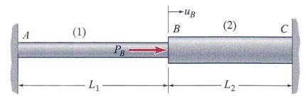
Figure 2.2.a
A. General Observations
The areas of the two rod segments are:

![]()

![]()
B. Calculations
B.1 Free-Body Diagram
The constraint located at point A is
replaced by a horizontal reaction ![]() as shown in Figure 2.2.b.
as shown in Figure 2.2.b.
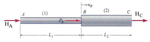
Figure 2.2.b
B.2 Reaction Calculation
The equation of equilibrium used is the projection of all
axial forces on the horizontal axis![]() :
:
![]()
The equation contains
two (2) unknown reaction forces ![]() and
and![]() . Consequently,
the system is a statically indeterminate. An additional equation is necessary. This is equation is geometrical in
nature and represents the fact that the total elongation of the beam is zero.
. Consequently,
the system is a statically indeterminate. An additional equation is necessary. This is equation is geometrical in
nature and represents the fact that the total elongation of the beam is zero.
![]()
Considering that the calculation of the displacement starts
at point A, ![]() and the axial displacement at
the end B of the interval
and the axial displacement at
the end B of the interval![]() , representing the steel rod, is calculated as:
, representing the steel rod, is calculated as:

At the left end of the ![]() interval the axial displacement is expressed as:
interval the axial displacement is expressed as:

This way the second equation is obtained as:
![]()
and by substituting the flexibility coefficients ![]() and
and ![]() into the
expression of the axial displacement
into the
expression of the axial displacement ![]() the following algebraic system is obtained:
the following algebraic system is obtained:
![]()
![]()
The solutions, representing the two reactions, ![]() and
and ![]() , are found:
, are found:

Substituting the numerical data the reaction forces are calculated as:

![]()
![]()

![]()
![]()

![]()
![]()

![]()
![]()
B.3 The Axial Force Diagram
The axial force diagram is drawn in Figure 2.2.c.

Figure 2.2.c
The axial force on the interval ![]() is a constant tension
force
is a constant tension
force![]() ,
while on the interval
,
while on the interval ![]() is a constant
compression force
is a constant
compression force![]() .
It can be concluded that both segments of the rod are uniform-axial deformed members.
.
It can be concluded that both segments of the rod are uniform-axial deformed members.
B.3 Stress and Strain Calculation
The stress and strain in the interval![]() , where the rod is made of solid steel are obtained as:
, where the rod is made of solid steel are obtained as:
![]()
![]()
![]() tension
stress
tension
stress
![]()
![]() elongation strain
elongation strain
In a similar manner is calculated the stress and strain
pertinent to the interval ![]() representing the
aluminum made rod.
representing the
aluminum made rod.
![]()
![]()
![]() compression
stress
compression
stress
![]()
![]() elongation
strain
elongation
strain
B.4 Calculation of the axial displacement
The displacement ![]() of the point
of the point![]() , the right end of the steel segment, is calculated:
, the right end of the steel segment, is calculated:
![]()
![]()
![]()
where the displacement at the origin of the interval ![]() and
and![]() ,
because the point is constraint against the horizontal movement.
,
because the point is constraint against the horizontal movement.
B.5 Verification of the Rod
The verification of the rod segments is conducted as:
for the steel segment
![]()
![]() ok
ok
where ![]() is the brass allowable
stress,
is the brass allowable
stress, ![]() is the brass yield
stress which can be found in Appendix 1.2, and is
is the brass yield
stress which can be found in Appendix 1.2, and is ![]() the safety factor .
For this calculation
the safety factor .
For this calculation ![]() and
and![]() .
.
for the aluminum segment
![]()
![]() ok
ok
where ![]() is the brass allowable
stress,
is the brass allowable
stress, ![]() is the aluminum yield
stress which can be found in Appendix 1.2, and
is the aluminum yield
stress which can be found in Appendix 1.2, and ![]() is the safety factor . For this calculation
is the safety factor . For this calculation ![]() and
and ![]() .
.
Problem 2.3
A rigid beam AB, shown in Figure 2.3.a, is supported by two vertical
rods made of steel with a modulus of elasticity E=200 GPa. The support rod
located at the end A has a diameter d1=25 mm. The weight of the beam
AB is negligible and is loaded at point C with a concentrated force P = 60 kN.
Calculated: (a) the diameter, d2, of the hanger located at the end
B, considering that the relation between the vertical displacement at the ends of
the beam ![]() , (b) under same condition the vertical displacement in node
C, (c) if the hanger located at end B of the rigid beam has a diameter d2=20
mm, what should be the position of the concentrated load P for relation
, (b) under same condition the vertical displacement in node
C, (c) if the hanger located at end B of the rigid beam has a diameter d2=20
mm, what should be the position of the concentrated load P for relation ![]() to be true, and (d)
the axial stresses in the hangers considering the conditions stipulated in the
previous question.
to be true, and (d)
the axial stresses in the hangers considering the conditions stipulated in the
previous question.
A. General Observations
A.1 The steel rod (1) has a length ![]() and diameter
and diameter![]() ,
while for the steel rod (2) only the length is known
,
while for the steel rod (2) only the length is known![]() .
Both rods are made of steel with a modulus of elasticity of steel
.
Both rods are made of steel with a modulus of elasticity of steel![]() .
.
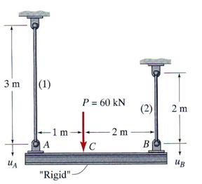
Figure 2.3.a
A.2 The vertical concentrated force ![]() is located at point
is located at point ![]() at a distance of
at a distance of ![]() from the left end. The total distance
in-between the rigid beam supports is
from the left end. The total distance
in-between the rigid beam supports is![]() ,
while the distance from the application point
,
while the distance from the application point ![]() to point
to point ![]() is
is![]() .
.
B. Calculations
B.1 Free-Body Diagram
The rigid beam ![]() is supported at ends
is supported at ends ![]() and
and ![]() by two steel rods which are playing the supporting role for
the beam. Sectioning the rods and replacing them by two corresponding axial
forces
by two steel rods which are playing the supporting role for
the beam. Sectioning the rods and replacing them by two corresponding axial
forces![]() and
and![]() , the free-body diagram of the system is obtained as shown in
Figure 2.3.b.
, the free-body diagram of the system is obtained as shown in
Figure 2.3.b.
B.2 Reactions Calculation
Two moment equations are written:
![]()
![]()
![]()
![]()
![]()
![]()
![]()
![]()
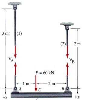
Figure 2.3.b
The two equilibrium equations are containing two unknowns,
the forces ![]() and
and![]() , and consequently, the system is statically determinate.
, and consequently, the system is statically determinate.
The verification of the reaction forces is done using the equilibrium equation of the projection of the forces on the vertical direction:
![]()
![]()
![]()
B.3 Calculation required by question (a)
The axial forces in the rods are tension type forces:
![]()
![]()
![]()
![]()
![]()
![]()
Because the axial forces in the rods and they have constant areas, both rods are uniform-axial deformed members. The flexibility coefficients are obtained as:


The geometrical condition required is:


Because the rod diameter is always a positive value, from the two above solutions only the positive value is a valid solution. Consequently, the diameter of the rod (2) is calculated as:


![]()
B.4 Calculations required by question (b)
The vertical displacement ![]() is composed from two components: one elastic and equal with
the vertical displacement
is composed from two components: one elastic and equal with
the vertical displacement ![]() and other rigid induced by the rigid rotation of the beam in
the vertical plane. The elastic vertical displacement
and other rigid induced by the rigid rotation of the beam in
the vertical plane. The elastic vertical displacement ![]() is calculated:
is calculated:
![]()
![]()
![]()
where 
![]()
![]() is the flexibility coefficient of the
rod (1).
is the flexibility coefficient of the
rod (1).
The vertical displacement ![]() is obtained:
is obtained:

![]()
![]()
B.5 Calculations required by question (c)
The geometrical condition imposed is written as:


The flexibility coefficient of the rod (2) is calculated
considering that the rod diameter is![]() :
:
![]()
![]()

![]()
![]()
The position of the concentrated force measured from point ![]() is obtained by substituting the previously
calculated flexibility coefficients:
is obtained by substituting the previously
calculated flexibility coefficients:

![]()
![]()
B.6 Calculations required by the question (d)
The axial forces in the hangers are:
![]()
![]()
![]() for
rod (1)
for
rod (1)
![]()
![]()
![]() for rod (2)
for rod (2)
The axial stresses are obtained:

![]()
![]() tension stress in rod (1)
tension stress in rod (1)

![]()
![]() tension stress in rod (2)
tension stress in rod (2)
B.7 Verification of the rods
Considering that the steel yielding stress and the
safety coefficient employed are ![]() and
and![]() , respectively, the allowable steel stress is calculated as:
, respectively, the allowable steel stress is calculated as:

![]()
![]()
Consequently,
![]() the
rod (1) is ok
the
rod (1) is ok
![]() the
rod (2) is ok
the
rod (2) is ok
Problem 2.4
The system shown in Figure 2.a is composed of a rigid beam
AD, pinned into the wall at point A, and two unequal linear elastic rods, BE
and CF, made of steel with a modulus of elasticity ![]()
![]() . The steel rods lengths and areas are
. The steel rods lengths and areas are ![]()
![]() and
and![]()
![]() , and,
, and, ![]()
![]() and
and![]()
![]() , respectively. The system is loaded with by vertical force
, respectively. The system is loaded with by vertical force![]() acting at point D. The steel rods and force
acting at point D. The steel rods and force![]() locations are determined by the following distances measured
from point A:
locations are determined by the following distances measured
from point A: ![]()
![]() ,
,![]()
![]() and
and![]()
![]() , respectively. What
is the allowable force
, respectively. What
is the allowable force ![]() supported by the
system if the allowable normal stress for steel is
supported by the
system if the allowable normal stress for steel is![]()
![]() .
.
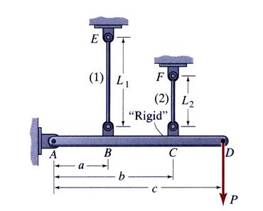
Figure 2.a
A. General Observations
The system illustrated in Figure 2.a is geometrical defined by the data contained in the text.
B. Calculations
B.1 Free-Body Diagram
The rigid beam ![]() is supported at the ends
is supported at the ends![]() and
and ![]() by two steel rods, which are playing the supporting role for
the beam, together with the pinned support located at point
by two steel rods, which are playing the supporting role for
the beam, together with the pinned support located at point![]() . Sectioning the rods and replacing them by two corresponding
axial forces
. Sectioning the rods and replacing them by two corresponding
axial forces![]() and
and![]() , and substituting the constraints introduced by the pinned support
by its corresponding reaction forces,
, and substituting the constraints introduced by the pinned support
by its corresponding reaction forces, ![]() and
and ![]() , the free-body diagram of the system is obtained and illustrated
in Figure 2.b.
, the free-body diagram of the system is obtained and illustrated
in Figure 2.b.
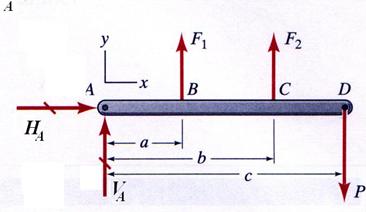
Figure 2.b
B.2 Reactions Calculation
The following equilibrium equations are written:
![]()
![]() no
axial force
no
axial force
![]()
![]()
![]()
![]()
The last two equilibrium equations contain three unknown
reaction forces![]() ,
, ![]() and
and![]() . The system is
statically indeterminate. In order to find these unknown quantities one additional equation is necessary. This equation is obtained from the
deformation compatibility condition schematically described in Figure 2.c.
. The system is
statically indeterminate. In order to find these unknown quantities one additional equation is necessary. This equation is obtained from the
deformation compatibility condition schematically described in Figure 2.c.
Because the beam AD is rigid, purely geometric relations between
the rod elongations,![]() and
and![]() , and the rotation angle
, and the rotation angle![]() are written as:
are written as:
![]()
![]()
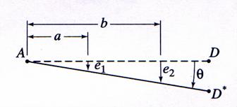
Figure 2.c
Using the elongation expressions the forces in the rods are calculated as:
![]()
![]()
![]()
![]()
where the stiffness coefficients, ![]() and
and![]() , are calculated from the geometrical and material properties
characteristics of the rods as:
, are calculated from the geometrical and material properties
characteristics of the rods as:

![]()
![]()

![]()
![]()
Substituting the expressions of the rod forces into the last
two equilibrium equations the three original unknowns,![]() ,
,![]() and
and ![]() , are replaced with two unknowns,
, are replaced with two unknowns, ![]() and
and![]() . The equilibrium equations are then written as:
. The equilibrium equations are then written as:
![]()
![]()
![]()
Solving the algebraic system, the two unknowns are found as:

The axial forces in the rods are calculated:


To find the force ![]() producing an allowable stress
producing an allowable stress ![]() in the rods the following equations are written:
in the rods the following equations are written:

![]() for rod (1)
for rod (1)

![]() for rod (2)
for rod (2)
The allowable force![]() for the entire system is:
for the entire system is:
![]()
![]()
![]()
The vertical displacements at point ![]() and
and ![]() are then calculated:
are then calculated:

![]()

![]()
Problem 2.5
An axial load P is applied to a tapered circular rod of length L as shown in Figure 2.5.a. The variation of the rod radius along its length is expressed as:

where ![]() is the radius at the
left end cross-section.
is the radius at the
left end cross-section.
Symbolically express: (a) the axial stress![]() , (b) the elongation strain
, (b) the elongation strain![]() and (c) the total elongation
and (c) the total elongation![]() . Apply the above obtain expressions for the case when where
P = 9 kN, L = 2.50 m, r0 = 0.50 m and the rod is made of an aluminum
alloy for which E = 69 GPa.
. Apply the above obtain expressions for the case when where
P = 9 kN, L = 2.50 m, r0 = 0.50 m and the rod is made of an aluminum
alloy for which E = 69 GPa.
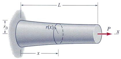
Figure 2.5.a
A. General Observations
The tapered aluminum rod is subjected to a non-uniform axial deformation, because the area is not constant along the length of the beam.
The variation of the area along its axis is expressed as:
![]()
where ![]() is the area
representing the cross-section at the left end of the rod (x=0).
is the area
representing the cross-section at the left end of the rod (x=0).
B. Calculations
B.1 Free-Body Diagram
The free-body diagram is illustrated in Figure 2.5.b.
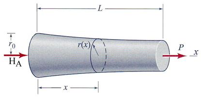
Figure 2.5.b
B.2 Reaction Calculation
The constraint located at the left end of the beam is
replaced by a horizontal concentrated reaction force![]() . The reaction force
. The reaction force ![]() is calculated using the equilibrium equation involving the
horizontal projection of all forces.
is calculated using the equilibrium equation involving the
horizontal projection of all forces.
![]()
![]()
![]()
The system is statically determinate.
B.3 Expression of the Axial Stress
The axial force in the rod is constant and represents a tension force:
![]()
The general expression of the axial stress in the rod is obtained as:

where ![]() is the axial stress in the cross-section located at the left
end of the rod.
is the axial stress in the cross-section located at the left
end of the rod.
B.4 Expression of the Axial Strain

where ![]() is the axial stress in the cross-section located at the left
end of the rod.
is the axial stress in the cross-section located at the left
end of the rod.
B.5 Expression of the Rod Total Elongation
The total elongation is obtained as:

B.6 Numerical Application
The following data is substituted in the above obtained expressions:
![]()
![]()
![]()
![]()
The reaction force is:
![]()
![]()
The area at the left end cross-section:
![]()
![]()
The axial stress and elongation strain at the left end cross-section are:

![]()

![]()
The variation of the axial stress and elongation strain are calculated in a number of twenty-one sections:
![]()
![]()


The maximum values are calculated in the right end cross-section (x = L):
![]()
![]()
![]()
![]()
The total elongation of the rod is:
![]()
![]()
The variation of the axial stress is illustrated in Figure 2.5.c.
Figure 2.5.c
Problem 2.6
A magnesium-alloy rod (Emag = 45 GPa) of diameter dm = 30 mm is encased by a brass tube (Ebra = 100 GPa) with outer diameter db. Both bars have an equal length L = 500 mm. An axial load P = 40 kN is applied to the resulting bimetallic rod. Assuming that that the magnesium rod and the brass tube are securely bonded to each other calculate: (a) the outer diameter db of the tube, if three fourths of the load P is carried by the magnesium rod and one fourth by the brass tube and (b) the total elongation of the bimetallic rod. The bimetallic rod is illustrated in Figure 2.6.
A. General Observations
A.1 It is assumed, due to the bondage between the materials, that the deformation at the right end cross-section of the bimetallic rod is equal for both materials.
A.2 The reaction force located at the left end of the rod is
not necessary to be calculated, because the distribution of the external force ![]() in-between the magnesium and brass cross-section is established.
in-between the magnesium and brass cross-section is established.
![]()
![]() for magnesium
for magnesium
![]()
![]() for brass
for brass
Note: It can be remarked that the bimetallic rod it is statically determined system, but because the modulus of elasticity is not constant for the entire length of the rod, the rod is subjected to a nonuniform-axial deformation.
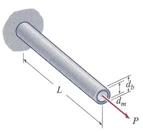
Figure 2.6
B. Calculations
B.1 Calculation of the brass exterior diameter ![]()
The equality of the deformation at the right end of the bimetallic rod is:
![]()
Using the flexibility coefficients ![]() and
and![]() , corresponding to magnesium and brass rods the displacements
equality is written as:
, corresponding to magnesium and brass rods the displacements
equality is written as:
![]()
where ![]() and
and ![]() .
.
Substituting the forces and the flexibility coefficients into the above equation, the expression of the brass area is obtained:

The area of the magnesium rod is calculated as:

![]()
![]()
and consequently, the area of the brass rod is obtained:

![]()
![]()
The exterior diameter of the brass tube is calculated from the following equation:

![]() because only the positive value makes sense.
because only the positive value makes sense.
B.2 Calculation of total elongation
The total elongation is equal to the displacement of the either material calculated at the right end of the rod. The calculation is conducted using the data pertinent for magnesium and is also verified using the brass data.
![]()
![]()

![]()
![]()
![]()
![]()
The verification using brass:

![]()
![]()
![]()
![]()
Note: It can be remarked that the deformation of both materials is 1.572*10-4 m and, this way, the geometrical condition imposed is also verified numerically.
Problem 2.7
A uniform circular cylinder of diameter d and length L is
made of a material with modulus of elasticity E. It is fixed to a rigid wall at
end A and subjected to a distributed external axial loading of magnitude p(x)
per unit length, as shown in Figure 2.7.a. The axial stress,![]() , varies linearly with x as shown in Figure 2.7.b. Determine:
(a) the expression for the distributed loading, p(x) and (b) the expression for
the axial displacement, u(x), of the cross section.
, varies linearly with x as shown in Figure 2.7.b. Determine:
(a) the expression for the distributed loading, p(x) and (b) the expression for
the axial displacement, u(x), of the cross section.
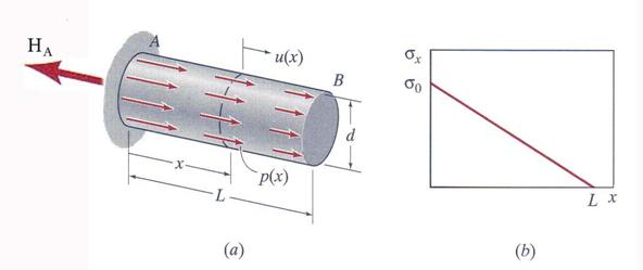
Figure 2.7
A. General Observations
A.1 The member is subjected to a nonuniform-axial deformation and it is statically determinate system.
A.2 The axial stress has the following expression (see Figure 2.7):
![]()
B. Calculations
The horizontal reaction force ![]() is calculated
as:
is calculated
as:
![]()
The axial force pertinent to a particular cross-section is obtained from the equilibrium as:

The axial stress is expressed:

Comparing the above expression with the expression given by the problem the following equation is written:
 and after the algebraic
manipulation the integral becomes:
and after the algebraic
manipulation the integral becomes:

Consequently,

It can be concluded that the linear variation of the axial stress is induced by a constant axially applied load.
Problem 2.8
Two rods are stress-free when welded together at point ![]() and welded to two
rigid walls at points
and welded to two
rigid walls at points ![]() and
and![]() . The geometrical and material characteristics of the two
rods are illustrated in Figure 2.8.a. Subsequently, rod (1) and rod (2) are
heated by an amount
. The geometrical and material characteristics of the two
rods are illustrated in Figure 2.8.a. Subsequently, rod (1) and rod (2) are
heated by an amount![]() and
and![]() , respectively from their initial installation temperature.
Determine an expression for the axial forces induced in each rod by the change
in temperatures.
, respectively from their initial installation temperature.
Determine an expression for the axial forces induced in each rod by the change
in temperatures.
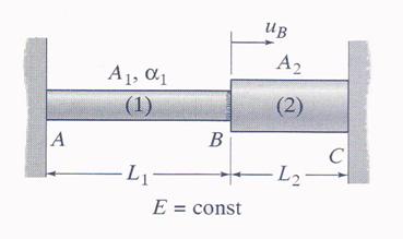
Figure 2.8.a
A. General Observations
A.1 The rods have the same modulus of elasticity![]() , but different expansion coefficients
, but different expansion coefficients ![]() and
and![]() .
.
A.2 It can be remarked the absence of any external load and the existence of a change in temperature
B. Calculations
B.1 Free-Body Diagram
The free-body diagram is illustrated in Figure 2.8.b.
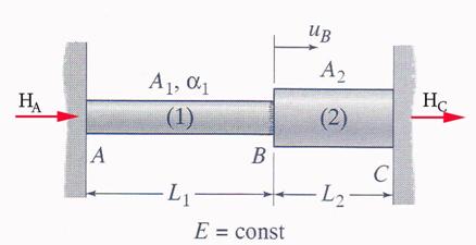
Figure 2.8.b
B.2 Reaction Calculation
The constraints located at the left and right end points,![]() and
and![]() , of the member are replaced by two horizontal reaction
forces,
, of the member are replaced by two horizontal reaction
forces, ![]() and
and![]() , respectively. The following equilibrium equation is
written:
, respectively. The following equilibrium equation is
written:
![]()
![]()
![]()
The system is statically
indeterminate and in order to calculate the reaction forces an additional
equation is necessary. This equation is the fact that the total elongation ![]() is zero:
is zero:
![]()
The expression of the displacements ![]() and
and ![]() are:
are:
![]()
![]()
where
![]() and
and ![]() are the flexibility coefficients
are the flexibility coefficients
The axial forces in the rods are:
![]() and
and ![]()
The elongation is calculated as:
![]()
From the condition imposing that the total elongation to be
zero, the reaction force ![]() is obtained:
is obtained:
![]()
Consequently, the reaction force ![]() is:
is:
![]() and the forces ion the
rods are:
and the forces ion the
rods are:
![]()
3 Proposed Problems
Problem 3.2
The three-part axially loaded member, shown in Figure 3.2,
consists of a tubular segment (1) with outer diameter ![]() and inner diameter
and inner diameter![]() , a solid circular rod segment (2) with diameter
, a solid circular rod segment (2) with diameter ![]() and a third solid circular rod segment (3) with diameter
and a third solid circular rod segment (3) with diameter![]() .
.
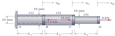
Figure 3.2
All three applied loads shown are acting along the
centroidal axis of the members. Considering that the rigid couplers have a
negligible length determine: (a) the axial stresses in each one of the three
respective segments, (b) the displacements in points B, C and D if all segments
have equal lengths L1 = L2 = L3 = 0.50 m and
the modulus of elasticity of the material is ![]() .
.
Problem 3.3
The diameter of the central one-third of a 50 mm diameter steel rod is reduced to 20 mm, forming a three-segment rod, as shown in Figure 3.3. For the loading shown, determine the displacements of the rod points B, C and D, respectively. The rod is made of a material which has the modulus of elasticity E = 200 GPa.
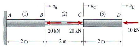
Figure 3.3
Problem 3.4
A column in a two-story building is fabricated from square structural steel tubing having a modulus of elasticity E = 210 GPa. The cross-sectional dimensions of the two segments are shown in Figure 3. Two axial loads acting along the centroidal axis of the column are applied to the column at levels A and B. Calculate: (a) the axial stress both segments of the column and (b) the total shortening of the column length
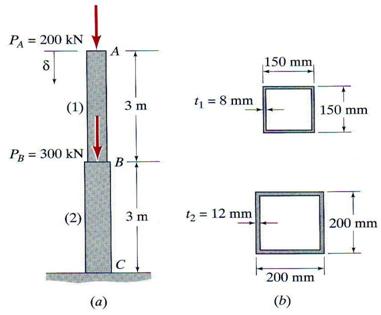
Figure 3.4
Problem 3.5
A three-segment stepped aluminum-alloy column is subjected to the vertical axial loads shown in Figure 3.5 The cross-sectional areas of the segments are A1 =3870 mm2, A2 =5810 mm2 and A3 =9035 mm2, respectively. The material modulus of elasticity is E = 69 GPa. Calculate: (a) the axial stresses in all three segments and (b) the vertical displacement of the column at nodes A, B and C under the given loading system.
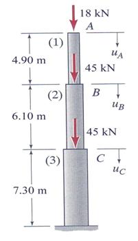
Figure 3.5
Problem 3.6
A uniform rod is subjected to three axial loads acting as shown in Figure 3.6 and is made of a material with a modulus of elasticity E = 70 GPa. What is the minimum allowable diameter of the cylindrical rod if the displacement at the right end D and the maximum axial stress in the rod can not excide 5 mm and 80 MPa, respectively?
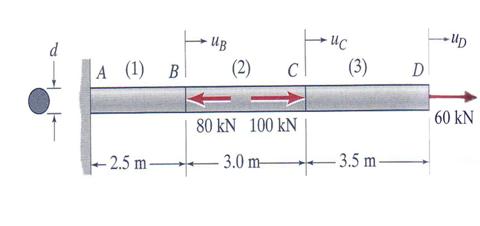
Figure 3.6
Problem 3.7
A 1.2 in diameter aluminum-alloy hangar, illustrated in
Figure 3.7, is supported by a steel pipe with an inside diameter of![]() =75 mm. The moduli of elasticity for the steel pipe and
hanger are Esteel =
=75 mm. The moduli of elasticity for the steel pipe and
hanger are Esteel =![]() MPa and Ealuminum =
MPa and Ealuminum =![]() MPa, respectively. Determine the thickness of the steel pipe
if the maximum axial displacement at the node C is 2.5 mm.
MPa, respectively. Determine the thickness of the steel pipe
if the maximum axial displacement at the node C is 2.5 mm.
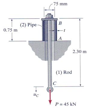
Figure 3.7
Problem 3.8
A 3.60 m rigid beam AB that weighs 0.80 kN supports an air conditioner that weighs Wair=45 kN. The beam is supported by hanger rods (1) and (2) located at its ends as shown in Figure 3.8.
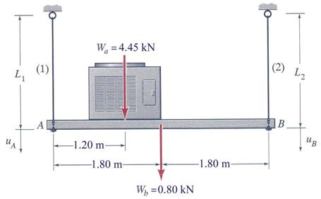
Figure 3.8
Conduct the following calculations: (a) if the diameter of
rod (1) is 95 mm what is the stress in the rod? (b) if the stress in rod (2) is
to be the same as the stress in rod (1), what should the diameter of rod (2)?
(c) what are the downward displacements at the ends of the rigid beam if the
rods length are L1 = L2 = 1.80 m and they are made of
steel with a modulus of elasticity E =210![]() 103 MPa?
103 MPa?
Problem 3.9
A hanger rod CD is attached to a rigid beam AB. The beam is supported at its ends by two hanger rods. Assuming that all tree hangers are identical and are made from the same material, calculate: (a) the axial stress in all tree hangers, (b) the vertical displacement of the points A, B, C and D.
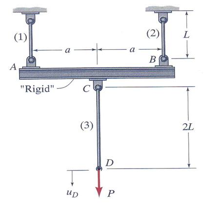
Figure 3.9
Problem 3.10
A commercial sign of weight W is supported by a structural system comprised from a rigid beam AB and a wire CD, as shown in Figure 3.10. The rigid beam has a negligible weight, while the wire has length L, cross-sectional area A, and modulus of elasticity E. Assuming that the attachment pin D is directly located above pin A, and when there is no load acting on the beam, the beam is in a perfect horizontal position calculate the following: (a) the axial stress in the wire CD when the sign is attached at points B and C of the beam, (b) the vertical displacement in point C of the beam.
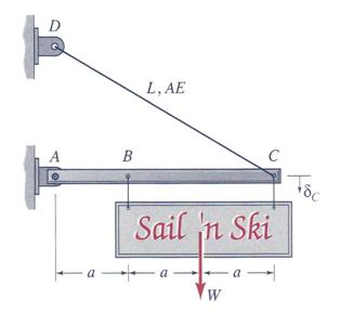
Figure 3.10
Problem 3.11
The inclined rod AB, shown in Figure 3.12, is pinned to a
fixed support at A and is pinned at the end B to a block that is forced to move
only horizontally when the load P is applied. Determine: (a) an expression for
the axial stress in the inclined rod as a function of P, L, E, A, and the angle![]() , (b) an expression for the horizontal displacement at the
end B.
, (b) an expression for the horizontal displacement at the
end B.
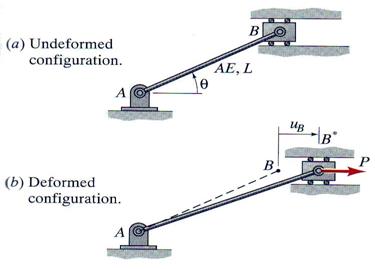
Figure 3.11
Problem 3.12 A bimetallic bar is made by bonding together two homogeneous rectangular bars, each having a width b, length L and moduli of elasticity of the bars are E1 and E2, respectively. An axial force P is applied to the ends of the bimetallic bar at location (y= yp, z = 0) such that the bar undergoes an axial deformation only. Assuming the following data: L = 1.5 m, b = 50 mm, t1 = 25 mm, t2 = 15 mm, E1 = 70 GPa, E2 = 210 GPa and P = 48 kN. Calculate: (a) the normal stress in each material, (b) the value of yp, (c) the elongation of the bar.
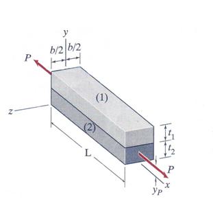
Figure 3.12
Problem 3.13
A bimetallic bar, shown in Figure 3.13, undergoes an axial deformation. The bar has the following geometrical and material characteristics: L = 2.55 m, b = 50 mm and h1 = h2 = 1.50 mm and E1=210 GPa. Calculate: (a) the modulus of elasticity E2 if the load P is applied at 10 mm, and (b) the total elongation of the bar for a load of P = 9 kN.
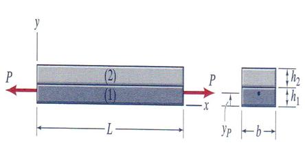
Figure 3.13
Problem 3.14
A steel pipe is filled with concrete, and the resulting column is subjected to a compressive load P = 360 kN. The pipe has an outer diameter of 325 mm and an inside diameter of 305 mm. The elastic moduli of the steel and concrete are: Estel = 210 GPa and Econc = 25 GPa. Determine: (a) the stress in the steel and the stress in the concrete due to this loading, (b) the shortening of the column if its initial length is L = 3.70 m, (Ignore- radial expansion of the concrete and steel due to Poisson's ratio effect.)
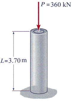
Figure 3.14
Problem 3.15
A homogenous rod of length L and elasticity modulus E is a
conical frustum with diameter d(x) that varies linearly from d0 at
one end to 2*d0 at the other end, with d0 << L. An axial
load P is applied to the rod, as shown in Figure 3.15. Determine analytical
expressions for: (a) the stress distribution,![]() , on an arbitrary cross section and (b) the elongation of the
rod,
, on an arbitrary cross section and (b) the elongation of the
rod, ![]() .
.
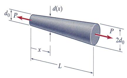
Figure 3.15
Problem 3.16 A uniform circular cylinder of diameter
d and length L is made of a material with modulus of elasticity E and specific weight![]() . It hangs from a rigid ceiling as shown in Figure 3.16.
Determine: (a) the expression of the axial stress
. It hangs from a rigid ceiling as shown in Figure 3.16.
Determine: (a) the expression of the axial stress![]() , (b) the expression of the strain
, (b) the expression of the strain![]() , (c) the expression of the displacement
, (c) the expression of the displacement![]() and (d) the compression force necessary to be applied in
order to return the bar at its initial length.
and (d) the compression force necessary to be applied in
order to return the bar at its initial length.
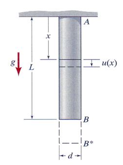
Figure 3.16
Problem 3.17
A steel pipe with outer diameter do = 50 mm, and inner diameter di = 38 mm and a solid aluminum-alloy rod of diameter d = 19 mm form a three-segment system that undergoes axial deformation due to a single external load PC = 55 Kn acting on a collar at point C, as shown in Figure 3.17. Considering the following data: L1 = L2 = 0.75m, L3 = 1.20 m, E1 = 210 GPa and E2 = E3 = 69 GPa, calculate: (a) the axial stresses induced in all three segments and (b) determine the axial displacement at points B and C.
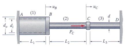
Figure 3.17
Problem 3.18
A three-segment rod is attached to rigid supports at ends A and D and is subjected to equal and opposite external loads P at nodes B and C, as shown in Figure 3.18. The rod is homogeneous and linearly elastic, with modulus of elasticity E. Assuming A1 = A3 = A and A2 = 2A, L1 = 2L and L2 = L3 = L, calculate: (a) the axial stresses in all tree segments and (b) the horizontal displacements at nodes B and C, respectively.
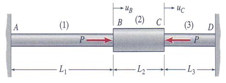
Figure 3.18
Problem 3.19
A rigid beam AD, supported by a pin at its end point D and attached
by the two vertical steel rods at points A and C, is loaded by a vertical load
P at point B. Neglecting the weight of the beam and assuming that the support
rods are stress-free when P = 0, calculate: (a) the forces F1 and F2
in the support rods after load P is applied, (b) the deformation of the
supporting and (c) the expressions previously obtained if A1 = A2
= 500![]() , L1 = 1m, L2 = 2m , E1 = E2
= 210 GPa, P = 50 kN, a = 0.50 m and b = 1.5 m.
, L1 = 1m, L2 = 2m , E1 = E2
= 210 GPa, P = 50 kN, a = 0.50 m and b = 1.5 m.
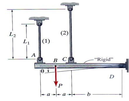
Figure 3.19
Problem 3.20
A rigid beam AD, shown in Figure 3.20, is supported by a smooth pin at B and by two vertical rods attached to the beam at points and C. Neglecting the weight of the beam and assuming that the rods are stress-free when P = 0. Considering that A1 = 650 mm2, A2 = 325 mm2, L1 = L2 = 1.25 m, a = 0.60 m, b = 1.25m, E1 = E2 = 69 GPa and P = 22.70 kN, determine: (a) the axial forces in the support rods, (b) determine the axial stress in each support and (c) calculate the elongation of the support rods.
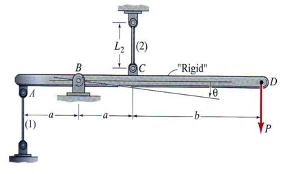
Figure 3.20
Problem 3.21
A rigid beam AD, shown in Figure 3.21, is supported by three identical vertical rods that are attached to the beam at points A, C, and D and loaded in node B with a vertical concentrated load P. Assuming that A = 650 mm2, L = 1.50 m, a = 0.50 m, b = 1.00 m, c = 1.50 m, E = 210 GPa and P = 45.5 kN, calculate: (a) the axial forces in the support rods and (b) the vertical displacements at nodes A, B, C and D.
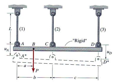
Figure 3.21
Problem 3.22
The rod composed from two segments as shown in Figure 3.22,
is attached to rigid walls at A and C. Determine expressions for the stresses
pertinent to both segments resulting from a uniform temperature increase ![]() of the entire rod. Numerical application: A1 =
1000 mm2, A2 = 1500 mm2, L1 = 2 m,
L2 = 1.5 m, E1 = 210 Gpa, E2 = 120 GPa, a1 = 12*10-6 and a2 = 8.0*10-6 and
of the entire rod. Numerical application: A1 =
1000 mm2, A2 = 1500 mm2, L1 = 2 m,
L2 = 1.5 m, E1 = 210 Gpa, E2 = 120 GPa, a1 = 12*10-6 and a2 = 8.0*10-6 and ![]() = 30
= 30![]() .
.
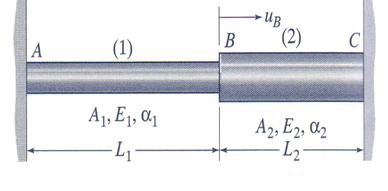
Figure 3.22
Problem 3.23
A three-segment rod shown in Figure 3.23 is rigidly attached to walls at points A and D. Subsequently, the middle segment is heated by an amount, while the segments (1) and (3) are kept at their original temperature. Using the notation shown in Figure 3.23 and considering the system free at stress at the installation, calculate the stresses in the segments and the axial displacements at points B and C.
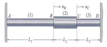
Figure 3.23
Problem 3.24
A steel pipe with outer diameter do, and inner
diameter di and a solid aluminum-alloy rod of diameter d form a
three-segment system as shown in Figure 3.2 The system is considered stress
free when is welded to the rigid supports at points A and D. The installation
temperature ![]() is recorded.
Subsequently, the aluminum rod is cooled by 100F (
is recorded.
Subsequently, the aluminum rod is cooled by 100F (![]() ), while the steel pipe is held at the initial temperature
), while the steel pipe is held at the initial temperature![]() . Assuming do = 50 mm, di = 38 mm, d = 19 mm, L1 = 1.25 m, L2
= L3= 0.75 m, E1 = E3 = 210 GPa, E2
= 69 GPa, a1 = a3 =
6.5*10-6 and a2
. Assuming do = 50 mm, di = 38 mm, d = 19 mm, L1 = 1.25 m, L2
= L3= 0.75 m, E1 = E3 = 210 GPa, E2
= 69 GPa, a1 = a3 =
6.5*10-6 and a2
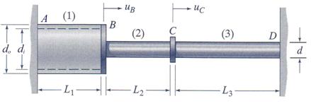
Figure 3.24
Problem 3.25
The mechanical system shown in Figure 3.25 is composed from two identical steel rods (A = 40 mm2, E = 200 GPa, a = 12.0*10-6) and a 'rigid' beam AC. The beam is supported by a smooth pin at B. Assuming the two rods stress-free after installation, determine: (a) the axial stresses induced in rods if their temperature is decreased by 50C and (b) the small angle q through which the beam AC would rotate due to this temperature change.
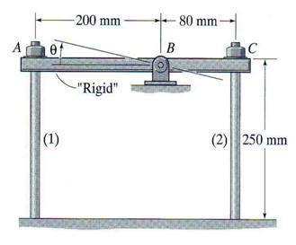
Figure 3.25
Problem 3.26
The steel rod of diameter 20 mm is held without any initial stresses between two rigid walls as illustrated in Figure 3.26. Determine the temperature drop DT at which the stress in the rod reaches 200 MPa. Use for the steel E=200 GPa and a = 12.0*10-6.
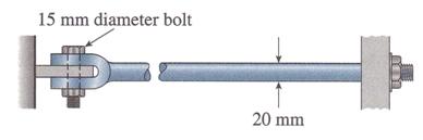
Figure 3.26
Problem 3.27
The bar AB, shown in Figure 3.27, is held between rigid supports and heated nonuniformly in such a manner that the temperature increase DT at distance x from end A is given by the expression DT (x) = DT1*(x/L)2, where DT1 is the increase in temperature at end B of the bar. Obtain a formula for the compressive stress in the bar. (Assume that bar has a length L and is made of a material with modulus of elasticity E and coefficient of thermal expansion a.)
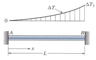
Figure 3.27
Problem 3.28
The copper bar AB of length 1.00 m is placed in position shown in figure 3.28 at room temperature. A gap of 0.2 mm exists between the end A of the bar and a rigid restraint. Calculate the axial compressive stress in the bar if the temperature is raised 90F. Use for copper the following material constants: E=110 GPa and a = 9.8*10-6.
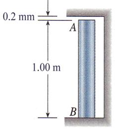
Figure 3.28
Problem 3.29
Three identical springs, 10 in. apart, are attached to a horizontal rigid bar at points A, B, and C, as illustrated in Figure 3.29. Three vertical loads of magnitudes 138 N, 45 N and 31 N act at points A, B, and C, respectively. Calculate the angle of rotation q (degrees) of the rigid bar if the spring stiffness k is 14 N/m.
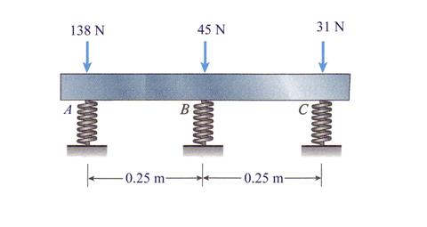
Figure 3.34
Problem 3.30
The rigid bar ABCD, shown in Figure 3.30, is pinned at point B and supported by springs at A and D. The springs at A and D have stiffnesses k1 = 11.20 kN/m and k2 = 36.75 kN/m, respectively. The dimensions a, b, and c are 0.45 m, 0.90 m, and 0.35 m, respectively. A load P acts at point C. Determine the maximum permissible load Pmax if the angle of rotation of the bar due to the action of the load P is limited to 2.
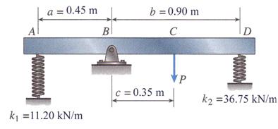
Figure 3.30
|
Politica de confidentialitate | Termeni si conditii de utilizare |

Vizualizari: 6832
Importanta: ![]()
Termeni si conditii de utilizare | Contact
© SCRIGROUP 2025 . All rights reserved