| CATEGORII DOCUMENTE |
| Bulgara | Ceha slovaca | Croata | Engleza | Estona | Finlandeza | Franceza |
| Germana | Italiana | Letona | Lituaniana | Maghiara | Olandeza | Poloneza |
| Sarba | Slovena | Spaniola | Suedeza | Turca | Ucraineana |
The need for effective and positive boost controls in a turbocharger system is brought about by the turbo's characteristic of increasing its rate of airflow faster than the ability of the engine to accept that flow. If unchecked, the turbo can quickly produce damagingly high boost pressures that lead to engine knock. The methods and details by which boost pressures are held in check are key elements in the success of any turbo system design.
Boost-control devices vary in style and effectiveness, from the angle of the driver's right foot to the sophisticated variable area turbine nozzles. The following discussion will outline the schemes and their merits for keeping boost production under reasonable limits.
Boost can be controlled by creating a restriction for either intake flow or exhaust flow. On the intake side, simply drawing through or pumping through a calibrated (by trial and error) orifice at the compressor inlet or outlet, respectively, can limit the flow so boost won't get out of hand. A slightly more clever device varies flow area as boost rises, so nonboosted operation is wide open. In-take charge temperatures will rise with this control, because the boost made will be from less air let in: thus the pressure ratio and temperature are greater. The restrictor will also work on the exhaust side. Again, the calibrated orifice will limit the flow, as the turbo is free to make huge amounts of boost, only to ,scrap the flow at the orifice.
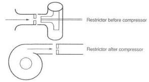
Fig. 12-1. Boost can be controlled by a compressor inlet or outlet restrictor. While effective, this increases heat and is a bad idea.
Fig. 12-
This restrictor can take the form of a large washer at the turbine outlet or even a muffler that hates performance. Any restriction to exhaust flow will drive combustion chamber temperatures up, because exhaust back pressure, and thus reversion, will be greater.
The fundamental notion of adding a turbocharger to increase flow through an engine and then adding a restrictor to control that flow must, in the final analysis, be considered a dopey scheme. No Formula 1 cars have flow restrictors.
A rather sophisticated radiator cap can be used as a boost-control device. Generally, these types of controls will prove inaccurate and often noisy. While far superior to any form of restrictor, these valves probably have their greatest value as safety controls in the event of a wastegate failure. They can commonly be found on production turbo cars as overboost safety devices. The vent valve has no business being a primary boost-control device. Furthermore, it cannot be used on a draw-through carb system, as it would be required to vent a fuel/ air mixture.
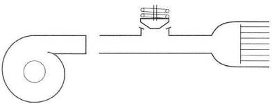
Fig. 12-3. Boost pressure can be vented after work is done to create it. Effective, but a bad idea.
The wastegate derives its name from the fact that it functions by wasting a portion of the exhaust energy. By wasting, or bypassing, a controlled amount of exhaust gas energy around the turbine, the actual speed of the turbine, hence the boost, can be controlled. Imagine the wastegate, then, to be nothing more than an exhaust bypass valve that allows only enough exhaust gas flow to the turbine to produce the desired boost,
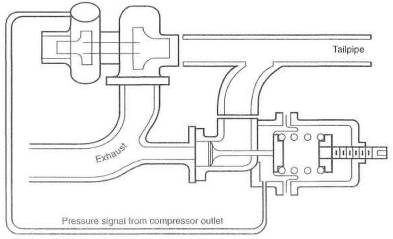
Fig. 12-4. The wastegate. This is the way to control boost with the classic turbocharger.
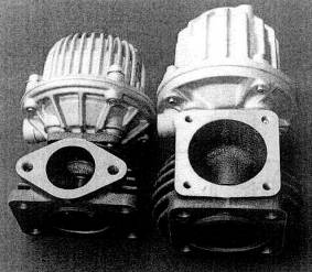
Fig. 12-5. Two excellent examples of wastegates from HKS
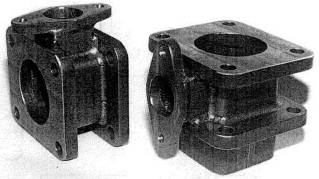
Fig. 12-6. Adapters to place a wastegate between the turbo and the manifold
Although the wastegate is currently the best choke for the job of boost control, it is not a perfect concept. That it functions by wasting energy is obviously a flaw. A second flaw is the need for the wastegate valve to start opening quite early in the boost rise time, so it will reach a position to stabilize boost when boost reaches the desired maximum. In other words, a wastegate set at 10 psi will usually start to open at about 5 psi and clearly waste a bunch of energy that could otherwise be used to speed the turbo up. Trying to gain turbine rpm while the wastegate valve is open is, in part, chasing one's tail.
The thousand-horsepower Formula 1 cars used wastegates, and so does every proper turbo system in the world. Until the VATN-controlled turbo becomes widely available at a reasonable cost, the wastegate is the best boost control.
Two styles of wastegate currently exist: integral and remote. Integral implies that the wastegate is built into the turbocharger itself. The remote can be placed wherever one feels the need. Or, at least, in a more ideal place.
The decision as to which style to employ is one of balance between economics and performance. The nod on economics goes to the integral style. The performance advantage, while small, is usually with the remote wastegate. Show me an integral wastegate on a race car.
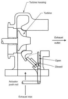
Fig. 12-7. The integral wastegate is inexpen-sive and easy.
Fig. 12-8. The remote wastegate is the best of the boost-control solutions.
One of the key Items in integrating the wastegate into the system is the location of the exhaust gas bleed-off from the exhaust manifold. This feature is critical, because it determines such things as load balance between cylinders, accurate and quick response of the gate, and, in part, turbine inlet pressure. The bleed-off must vent from a location where the pulses from all cylinders have been collected. This virtually always means the manifold, close to the turbine mounting flange. Symmetry and easy flow paths are ideals for laying out a wastegate system.
It is vital that exhaust gases be given an easy job of changing direction from the route toward the turbine to the bypass through the wastegate. If flow has any difficulty whatsoever changing direction to exit through the wastegate, the ability to control boost in the higher rev ranges may simply disappear.
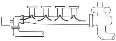
Fig. 12-9. The wastegate that does not vent from all cylinders uniformly is a bad idea. Nor should it cause reversal of flow from the turbo, as here.
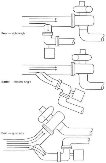
Fig. 12-10. Bleed angles into wastegates are important, to allow exhaust gas to flout easily out of the system.
Exhaust gas return
from the wastegate to the tailpipe after the turbine should receive the same
forethought as gas entering the wastegate. The principle here is to avoid
interfering with exhaust gas flow exiting the turbine. Interference will raise
exhaust back pressure, thus reducing power. An integral wastegate will usually
channel bypassed exhaust gas back into the system immediately aft of the
turbine wheel. This is acceptable for economic reasons but is not in the best
interest of power. A few integral wastegate designs, like some models of the
Japanese IHI, have provided a separate exhaust pipe for the bypassed gases.
When this separate pipe is available, it should be taken advantage of and
routed some distance down the tailpipe before being dumped back into the main
exhaust system. A minimum distance would be
As discussed in Chapter 11, the ideal circumstance for bypassed gases from the wastegate is a completely separate tailpipe. This offers the most positive wastegate response, lowest back pressure, and no interference with flow through the turbine.
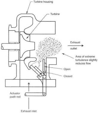
Fig. 12-11. Integral wastegates usually dump vented gases immediately behind the turbine and create high turbulence, reducing overall flow.
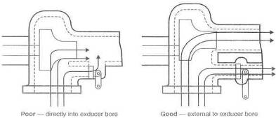
Fig. 12-12. Integral wastegates that keep vented gas away from primary exhaust gas permit superior power output.
Perhaps not cheap or easy, but a maximum-effort turbo system will have a separate tailpipe for the wastegate, with suitable consider-ation given to thermal expansion of the tube without any cracking of the joint between tube and tailpipe
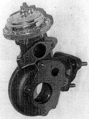
Fig. 12-
Boost pressure applied to the wastegate diaphragm is referred to as the actuator signal. The source of this signal can influence wastegate response, ultimate boost pressure, and, under certain circumstances, even fuel flow rates. It is therefore important to consider where this actuator signal should come from. It is vital to know and understand that the wastegate will control the pressure at the point where the actuator signal is taken from the system. If the signal is taken at the compressor outlet, that is the point in the system that will experience boost pressure dictated by the basic setting of the wastegate. Likewise, if the signal is taken from the exhaust pipe (don't laugh), pressure in the tailpipe at that point will, again, be dictated by the basic setting of the wastegate. It is known that pressure distribution through the engine/turbo system varies due to such flow-restricting devices as intercoolers, throttles, sometimes venturis, and just plain plumbing problems. Obviously, then, pressure through the entire system will vary based on the location of the actuator signal source. So, where to put the signal source?
Essentially, three choices exist for sourcing the signal: the compressor outlet, a plenum entering the throttle bodies, and the intake manifold. Each of these has merit and problems.
The signal originating at the compressor outlet offers the best control over the wastegate with regard to its response and ability to consistently control boost to a given value.
The bad side is that torque-curve rise will suffer slightly, as this source will create the earliest possible wastegate cracking point. This early cracking point will offer some relief thermally, because the entire system will virtually never see more boost than the basic setting of the wastegate. This can be important in avoiding a quick heat soaking of the intercooler.
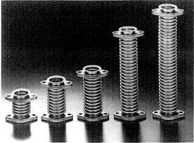
Fig. 12-14. Flexible wastegate vent tubes allow for extreme expansion and contraction caused by large temperature fluctuations through the wastegate.
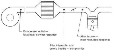
Fig. 12-15. The wastegate signal source can affect the system with respect to heat load and turbine response.
The intake plenum signal source will slightly improve boost response, since the turbo is free to make all the boost it can until the pressure reaches the signal source and is transmitted to the wastegate. The fact that the turbo is free to make a brief spike of boost will cause the intercooler to be hit by a greater slug of temperature. Greater temperature is always to be considered a negative. For a blow-through carburetor system, where the wastegate and fuel pressure regulator must see the same signal simultaneously, the plenum signal source is best.
Sourcing the signal from the intake manifold should be considered only when turbo response is of the highest importance and the short blast of extra heat can be tolerated or ignored.
All things considered, heat should be the controlling factor. Unless unusual circumstances dictate, hook the wastegate signal to the compressor outlet and call it a day.
A variety of design features influence the function and capability of the wastegate. Most wastegates on the market today have a good balance of features versus cost, but a close analysis of these features may show one unit to be superior to another for a specific application.
Common direction. One general characteristic all wastegates must have is a common direction for the pressures applied to the valve and diaphragm. Ex-haust gas pressure applied to the wastegate valve absolutely must push in the same direction as boost pressure applied to the diaphragm.
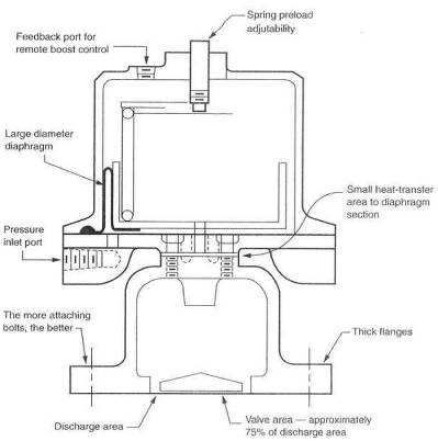
Fig. 12-16. Design considerations of a wastegate
Stability and consistency. The stability with which a wastegate controls boost pressure, and the wastegate's day-to-day consistency, are generally related to the ratio of the areas of the diaphragm and valve. All other things equal, the greater the ratio, the better the wastegate.
Heat isolation. Heat isolation is critical to the life expectancy of the wastegate, Heat isolation is, in part, where you choose to put the thing, but it is also very much a function of the path available for heat to get from the very hot valve area up to the diaphragm area. The idea is, of course, to keep the heat away from the fragile diaphragm. Heat travels through heavy sections of metal quickly; thus, the less material area between the two, the better. Aluminum conducts heat superbly, whereas stainless steel is lousy at it. Therefore, a stainless steel wastegate should treat the diaphragm to an easier life.
Cracking pressure. The cracking pressure of the wastegate is the pressure at which the valve first lifts off its seat. This pressure is usually one-half to one-third of the stabilizing (maximum boost) pressure. A high cracking pressure is important, because a fair amount of energy intended for the turbine will be vented out the wastegate as soon as it cracks, yet the turbo is not up to maximum boost. Thus the turbo's ability to gain boost after the cracking point is reached is slightly diminished.
Adjustability. Adjustability is a nice feature to have in any wastegate. This is
usually accomplished by a screw that changes the preload of the valve spring.
The nature of spring rates, free lengths, and compressed lengths usually dictates
a range of adjustment of the basic wastegate limited to about ![]() 2 psi without
changing the spring itself.
2 psi without
changing the spring itself.
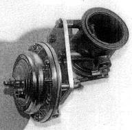
Fig. 12-17. This clever design by Turbonetics avoids the cracking pressure issue by using a throttle-plate wastegate valve.
Virtually all gate manufacturers offer a variety of springs for different boost pressures. Generally, remote wastegates offer an adjustment feature; integral units do not.
Mounting flange. Mounting flange stylos can be an important consideration when selecting a suitable gate. Rigid, strong, clamped-up flanges are long-term reliable. All else is somewhat less.
Turning up the boost is becoming the favorite pastime of serious power enthusiasts. It is simple to think in terms of making more power by just turning the boost screw. Alas, this is not the answer. The promise under which one must operate if one desires to turn up the boost is to remove some heat from the intake charge, make sure the air/fuel ratio stays correct, and, when possible, add octane. Then, and only then, is one entitled to turn up the boost to a new level that adds back to the system the same amount of heat that was taken out by improving the system's efficiency.
For example, a more
efficient intercooler that can remove another
Altered spring. A simple modification for a permanent change of boost level is to alter the spring in the wastegate actuator. This can be done in three different ways: shim the original spring to a higher preload, replace the original spring with a stiffer one, or add a supplementary spring to aid the original. Estimating the stiffness of the spring required for a specific boost gain is a bit of a lengthy calculation. Perhaps trial and error is easier if you are not keen on calculation. A relatively easy approach to selecting a supplementary spring is to choose one of approximately the same length as the original but about half as stiff. This will result in a boost setting about one-third higher than stock.
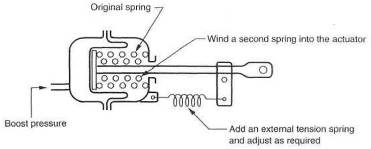
Fig. 12-
Dial-a-boost. Another easy form of variable boost control is the concept of dial-a-boost. This device is nothing more than a controlled leak in the actuator signal line. If, for example, a 2 psi leak can be created in the signal line, it would take 9 psi of boost to open a 7 psi wastegate. An adjustable leak can be created by using a pressure regulator as the leak adjustment. Turn the knob, vary the leak, and presto: dial-a-boost.
Two-level boost switch. Dial-a-boost with a variation can become a two-boost- level, high-and-low switch. Dial-a-boost works by creating a leak, and the leak can be turned on and off by a solenoid controlled by a switch from the cockpit. This same scheme could be expanded to any number of boost levels deemed necessary. The logic of two or three boost levels is not tough, but the logic of ten different ones would escape me.
Bleed orifice. Perhaps the simplest means yet devised of upping boost is the simple
bleed orifice that lets out. part of the signal the wastegate actuator receives.
Start with a bleed hole of approximately
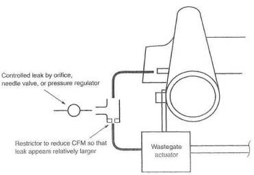
Fig. 12-19. The basic concept of the remote boost-change device.
Electronic/pneumatic wastegate controller. The electronic controls recently available for the wastegate offer an additional benefit. Not only do they provide several different boost pressures at the push of a button, they also keep the wastegate valve closed until desired boost pressure is reached. This is accomplished by blocking the pressure signal to the wastegate, preventing it from cracking open 5 or 6 psi before maximum boost. Boost rise from mid-range to maximum is significantly faster. While difficult to perceive in first gear, the benefits are obvious and substantial from third gear up.
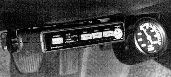
Fig. 12-20. The HKS Electronic Valve Controller is a multilevel boost-change device that also produces faster boost rise by blocking the signal to the wastegate until near-maximum boost is achieved.
It is hard to argue against some form of emergency boost control that will take over should the wastegate experience a failure. Don't think for an instant, however, that if this happens, the engine is destined to melt down. When a wastegate begins to fail, it does not take a rocket scientist to see the higher readings on a boost gauge and deduce that something is amiss. Nor does it take Mario Andretti to tell that the vehicle is accelerating a bit faster and that perhaps a change has occurred in something that merits a closer look. Fundamentally, if one blows an engine because of a failed wastegate, one ought to turn in one's driver's license. Nevertheless, it is easy to have an override safety, keep your foot in it, and just not worry about a thing;
Several schemes function satisfactorily as safety devices. In OEM turbo systems, these vary from pop-off radiator-style vent valves to electronic fuel cutoffs or ignition cuts. If one has done one's homework and wishes to raise the boost of an OEM system, the factory overboost safety device must be defeated, but it is still a good idea to install a new one to account for the higher boost level. The individual approach to blocking these devices is likely a search of the factory manual or consulting someone in the aftermarket who has done such tinkering.
If you are designing your own turbo system, it is also advisable to create an override safety device, A boost-pressure-sensitive switch can cut the 12-volt pulse to a coil, igniter, or fuel pump. Merely identify the proper wires, insert a pressure-actuated switch set 1-2 psi above the wastegate setting, and supply it with a boost signal. Killing the fuel supply is probably the better of the two choices. These devices can cause a jerking on and off if the foot is kept in it (as boost repeatedly comes down to a safe level, closing the circuit, which causes boost to rise again), but safety they do offer. This approach is not, of course, quick enough for carbureted engines and is therefore limited to those that are EFI-equipped.
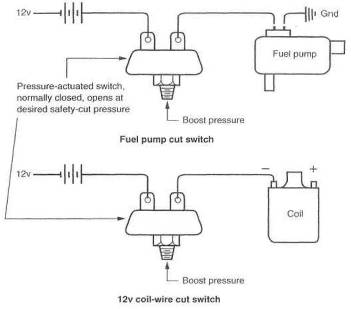
Fig. 12-21. Overboost protection can be achieved by cutting power to the coil or fuel pump.
Why is a wastegate important?
A gasoline-application turbo system must have a boost-control mechanism to prevent the possibility of too much boost causing damaging detonation. The wastegate is the standard-configuration turbo's only technically correct boost control. The only other viable alternative is the VATN turbocharger, which controls turbine speed, and thus boost, by vane position (see Chapter 16). This type of turbocharger has far greater technical merit than standard turbos with wastegates.
How should a wastegate integrate into the system?
A wastegate has two
plumbing requirements: where it vents From and where it vents to. The wastegate
should draw from the same area of the exhaust manifold as the turbo. The vent
from the wastegate should ideally have a separate exhaust pipe and muffler.
This causes the least disruption to the flow through the turbo and tailpipe.
The vent tube back into the tailpipe ought to be located well down the pipe
from the turbo, a minimum of
Are there any beneficial safety devices ?
Overrev and overboost back-up safety devices are good features. A detonation indicator is useful for the hearing impaired. A closed-loop detonation detection and correction system is a valuable safety addition.
|
Politica de confidentialitate | Termeni si conditii de utilizare |

Vizualizari: 1345
Importanta: ![]()
Termeni si conditii de utilizare | Contact
© SCRIGROUP 2025 . All rights reserved