| CATEGORII DOCUMENTE |
| Bulgara | Ceha slovaca | Croata | Engleza | Estona | Finlandeza | Franceza |
| Germana | Italiana | Letona | Lituaniana | Maghiara | Olandeza | Poloneza |
| Sarba | Slovena | Spaniola | Suedeza | Turca | Ucraineana |
At is easy to get smugly comfortable with the idea that you can design ideal pieces to fit into imaginary spaces in a beautiful and artistic manner. The smugness usually leaves abruptly when you are confronted with the prospect of placing all the items required for a proper turbo system underneath the hood of a modern automobile. The reality of the problem of finding not just space, but the best space and the logical spatial relationship for the components, can humble the cleverest of designers. The first part of this chapter offers guidelines for bringing all the pieces together into a theoretical, coordinated, least-compromise system. Hopefully, this will help you get past the initial fright of looking under the hood. The second part of the chapter deals with the design parameters of installing a turbo system on an actual car, the Acura NSX.
The first step is to define the specific performance objectives. Second is defining the system required to meet those performance objectives. Third is creating an outline of the components needed to build that system. A typical outline can take the following form, using a 300-350 cid Chevy V-8 as an example.
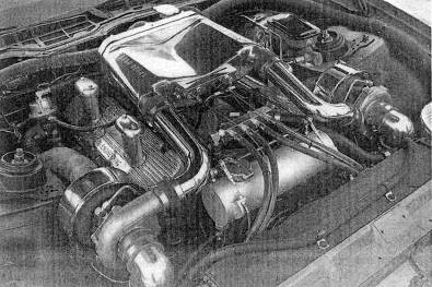
Fig. 17-1. Gale Banks produced this big-block Chevy twin with a water-based intercooler housed in the cast aluminum plenum atop a Holley carburetor.
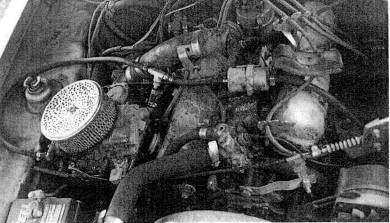
Fig. 17-2. Do not copy any features of this old draw-through on a
Performance objectives;
600 bhp @ 6500 rpm
650 ft-lb torque @ 3500 rpm
20 mpg @ legal cruise speed
93 octane fuel System requirements:
300-350 cid engine
pressure ratio of approximately 2.0
tixrbocharger(s)
wastegate (s)
intercooling
programmable electronic fuel injection
high-voltage ignition
bypass valves
Specific components:
Chevrolet 350 cid V-8 (four-bolt mains, forged-steel crankshaft, x.x compression ratio, aluminum cylinder heads)
turbocharger (brand, water-cooled bearing housing, compressor size, turbine size, exhaust housing style)
wastegate (brand, basic boost setting, valve size)
intercooler (air or water style, charge air flow area, heat exchange area. )
This outline should continue until the components, brands, and sizes are all defined. When the outline is complete, the scope of the task will be clearly spelled out.
Once the outline of the job is clear, the actual component positions can be studied and determined. Paper, pencil, some study and sketching will go a long way toward eliminating problem areas.
All aspects of the layout must give full consideration to the need or intention to seek a California Air Resources Board exemption order for the system. A prime factor is the position of the catalytic converter and the oxygen sensor. There is no need to move an oxygen sensor, but traditionally, the turbocharger is placed between the engine and converter. With respect to any certification, you need to consider converter light-off (the point at which it is hot enough to start working) as of foremost importance in order to pass the warm-up cycle emissions test.
Pig. 17-3. Jim Feulig built this marvelous
The first job is positioning the turbo. The factors contributing to the choice of position are as follows:
Is exhaust gas entry into the turbo from the engine as direct as possible? This will influence or dictate the manifold or header pipe design. Can a smooth, large-radius-bend exhaust manifold fit in the space dictated by the turbo position?
Does the position permit space for and easy installation of the turbine outlet pipe and proximity to the catalytic converter? The closer to the converter, the better.
Does the compressor inlet allow easy entry from the air filter and the outlet easy exit to the intercooler?
Can the wastegate be properly tied in to the exhaust manifold collector?
Will heat from the turbine damage any nearby components, and are heat shields necessary?
Is the turbo high enough for a gravity-powered oil drain to be adequate?
Does the turbo need support other than the exhaust manifold?
Does the position allow clearance to objects that could contact components of the turbo system when engine torque forces distortion into engine/drivetrain flex mounts?
Once the best combination (least compromise) of position requirements is determined, the turbo can be anchored by temporary hangers while installing connecting hardware.
The second job is building the defined intercooler and placing it into position. Considerations are as follows:
Is the spatial volume sufficient for a large enough intercooler?
Does the general layout of the vehicle require a water-based intercooler or some other unusual feature?
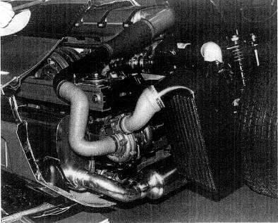
Fig. 17-4. Good basic plumbing from Porsche, as one would expect. The intercooler can get excellent ambient air from behind the rear wheel and is protected by a heavy wire-mesh screen.
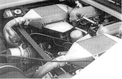
Fig. 17-5. The great Ferrari Turbo GTO used one wastegate to control two turbos. Note the integration of antisurge values into both compressor outlets. The intercoolers show good internal streamlining and generous core area, but ambient cooling air is sparse.
Can the tubes be routed conveniently to and from the intercooler, and do they meet flow requirements?
Will the cores receive adequate ambient airflow, or will they require air duets?
Is the position sale from road hazards?
Is the intercooler in front of the radiator bulkhead, if front-mounted? Does it block the least amount of airflow to the radiator (if applicable)?
The third job is defining and positioning the air filter. Use the filter manufacturer's recommendation on size versus horsepower. Keep in mind the following:
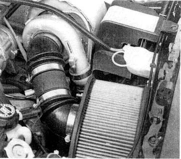
Fig. 17-6. Larger air filters are necessary for performance and to help keep thermal loads in check. Note the thermal blanket over the exhaust housing. The compressor inlet flex hoses need to be reasonably stiff to avoid being collapsed by the alight pressure drop through the filter.
The filter requires clean air but must be protected from puddle or splash water. However, cool ambient air is not essential if the system is properly intercooled.
The further the filter is from the vehicle occupants, the quieter it will be.
A bell-mouth-shaped transition from the filter to the flowmeter or compressor inlet tube is desirable.
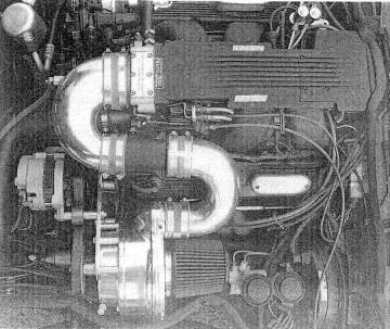
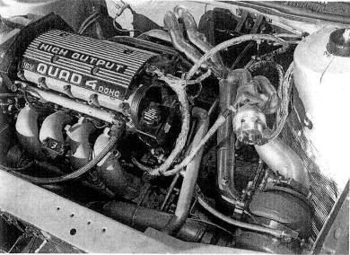
Fig. 17-7. Taking system air from directly above the exhaust manifold is not a good idea, particularly where no intercooler is present, A simple air duct to the front would lower the charge temperature about 50ºF.
The fourth job is the location of a muffler with an adequately large flow path. If the system is rear- or mid-engined, the muffler becomes key to the packaging, due to its relative size. If front-engined, the positioning requirements relax considerably.
The fifth job is creating a connection to the throttle body. This establishes the destination of the Lubes exiting the intercoolers. The throttle plate in the throttle body is a relatively high-drag point in the system. For this reason, particular attention must be given to smooth section changes in this area and avoidance of other drag-producing imperfections.
The sixth job is to design and build the exhaust manifolding. Factors to keep in mind include easy oil-line access, clearance to heat-susceptible parts, compressor inlet and outlet paths, turbine outlet space, and turbo section clocking problems due to an integral wastegate (if present). Spark plug and plug wire access need close attention.
Where possible, pipe-thread fittings should be chosen for simplicity and sure sealing. The less-than-wonderful aesthetics of pipe threads can easily be masked by sinking fittings up to the last thread.
All intersections of signal-line hoses should be made with brass tees. Signal lines should be silicone-based material, resistant to heat and hydrocarbons.
The locations of all components in the system must receive due consideration. When that has been done and done well, the major hurdle of bringing the components together into a system will have been accomplished.
Here we will further examine the design, development, construction, and testing procedures discussed in the previous sections in regards to creating a new twin turbocharger system for an Acura NSX. The validity of the lessons in this book can be determined by comparing the defined objective with the finished product.
For economy of operation and to more easily keep engine emissions within EPA/CARB certification limits, the engine has been kept absolutely stock.
The obvious hurdle presented by this project is the high compression ratio of the NSX engine, at 10.2 to 1. This value, in an engine powered by street fuel of 92 or 93 octane, dictates low maximum boost pressure to obtain long-term durability.
Any construction effort of this nature must consider the guidelines for engine system modifications drawn up by the U. S. Environmental Protection Agency and the California Air Resources Board. The decision to apply for an exemption order from CARB for the NSX turbo system for true street-legal status dictates several facets of the design:
All electronic engine management functions are to remain unaltered.
The original catalytic converters must remain stock and in the original
position.
Fuel system controls must function only when under boost,
Actual engine emissions must remain within CARB guidelines for the NSX.
Torque and power of the system should complement the engine's broad-range torque curve and substantial power. Honda/Acura spent considerable money and engineering talent on creating a broad torque curve, largely through use of a clever variable valve-timing mechanism.
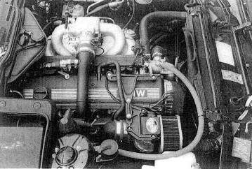
Fig. 17-8. This modest 5 psi system for the BMW 535i was designed with low maximum boost pressure for long-term durability. In order to get comparable durability, the Acura NSX engine will dictate a similarly modest system because of its high compression ratio.
To preserve the superb driveability offered by the NSX's torque curve, it will be necessary to achieve substantial boost at low engine speeds. This is a characteristic of smaller turbos. However, achieving high-rpm torque increases without huge exhaust gas back pressure losses dictates the need for a larger-than-normal turbocharger. These diametrically opposed requirements can be dealt with in three ways:
A variable area turbine nozzle turbo, which has the ability to act like a small turbo at low speeds and a large turbo at high speeds, thus potentially satisfying both requirements
Two turbos, utilizing one for low speed and both for high speed, where a twin scroll turbine is not available in a large enough size
A standard turbo with the best possible sizing between the two opposing requirements
Ordinarily, the factors discussed in Chapter 3 (vehicle cost and class, system cost, objectives) would influence which of these three options is selected. Lack of pizzazz rules out a system based on a standard turbo. With a twin sequential layout, performance is good, but complexity rivals a space shuttle's main engine.
A complicating factor is that space restrictions in the NSX dictate mounting the turbo low in the chassis, which is inadequate for the gravity oil-drain requirements of a standard turbo. The choice is then between installing sumps and pumps for return oil on a standard turbo or using the self-lubricating Aerocharger. The added attractions of the Aerocharger's fast response and good low-rpm boost make this an easy decision.
The original power rating of the NSX, while substantial, (275 bhp at 8000 rpm), still falls short of the desires of most buyers with $65,000 to spend on a performance automobile. Simple calculation of serious performance-car weight per horsepower suggests that the NSX can step into the high end of the supercar category with the addition of 100 bhp, which will require two Aerochargers, since no single unit is large enough to provide the desired airflow. An increase in base engine output of 36% will then be necessary through the turbo system:
![]()
The perceived value of an add-on system like this is always a balance of power gain versus cost, installation complexity, increased service requirements, and expectation of long-term durability degradation. The relatively low boost required (performance gain times atmospheric pressure, or 0.36 x 14.7 = 5.2 psi) for the anticipated 100 bhp gain suggests that the other value considerations will fall into line.
As mentioned in Chapter 3, after the field of available compressors is narrowed to two or three that appear, from their flow maps, to be in the right range of pressure ratio and cfm, with efficiency not below 60%, it is necessary to calculate which of the compressors is the more suitable. In this case, two sizes of Aerocharger will be examined: models 101 and 128,
Long-term durability
of an engine/turbo system is in part keyed to exhaust gas temperature. Although
a high temperature is able to really kick a turbine up to speed quickly,
performance must be weighed against durability. The size of the turbine will
depend partly on exhaust gas temperature. Heat distribution through the exhaust
system can be illustrated by the temperatures before and after the catalytic
converters. These measured a remarkably low
As described in
Chapter
The pulse duration of a fuel injector required to fuel a maximurn-torque pulse is useful information. This pulse duration will be compared to the engine cycle time to determine the method of supplying fuel to operate under boost. With the objective of a 36% torque increase, the fuel supply must be increased by 36% also. If a 36% increase in pulse duration does not exceed engine cycle time, it is possible to achieve the fuel flow increase by electronically extending the pulse durations. If the pulses are too long to permit this, a rising-rate fuel pressure regulator or an entirely reprogrammed fuel curve, us-ing larger injectors, will be necessary. The obvious difficulty of matching Acura's accuracy in fuel system calibration will likely point to the rising-rate regulator for the job. Another reason not to use the extended-pulse method is the inability of the NSX's ecu to interpret above-atmospheric pressure signals from the manifold air-pressure sensor.
Further test data were needed regarding this vehicle's emissions. Emissions were checked on a four-gas analyzer from a cold start and every 10 seconds thereafter until the vehicle was warmed up. Emissions plotted versus time are shown in figure 17-9.
It is necessary to know the time of one revolution, in order to compare it to the pulse duration of the fuel injector at maximum load, This comparison wilt determine whether the injector can stay open longer to feed the additional air supplied by the turbos.
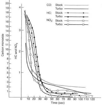
Fig. 17-9. Prior to the expensive emissions laboratory cold-start tests, it was considered advisable to run an inexpensive test on a four-gas analyzer. Results showed cold-start emissions essentially unchanged.
As indicated in Chapter 7, the time of one revolution can be determined either from figure 7-3 or by formula. Using the formula, let rpm = 8000, Then

The NSX's EFI is sequential, which reverts to nonsequential over approximately 3000 rpm, as discussed in Chapter 7. Therefore, pulse duration should be checked at over 4000 rpm. Actual pulse duration at maximum load was measured at 5.0 msec.
![]()
The inverse of the duty cycle minus one is the available increase in fuel flow from extending injector pulse duration. This is .5, or 50%. Therefore, we could hold the injectors open all the time and achieve a 50% increase in fuel flow. This is adequate for the 36% increase in airflow necessary to achieve the 36% performance gain (and, therefore, fuel flow) calculated earlier.
The fuel pressure required to operate at a 36% increase in airflow can be approximated by squaring the sum of one plus the airflow rate increase:
![]()
This shows that 85% more fuel pressure than stock will be required:
1.85 x 45 psi = 63 psi
where 45 psi is stock pressure for the NSX.
Preliminary test and calculation have shown that the fuel system can supply sufficient flow for the power desired by either increasing pulse duration or raising fuel pressure as a function of boost pressure. As the latter approach is less expensive, it is the prime candidate unless proven inadequate.
The Varicom VC200 acceleration computer was used to collect the following data:
0 to 60: 5,7 sec
1/4-mile time: 14,0 sec
1/4-mile speed:
Estimated bhp: 268
Determination of the best compressor Lor the job is a process of looking at whether the airflow and efficiency numbers are sufficient to push the required amount of air through the system.
The new pressure ratio will generally be close to the performance gain. Therefore, the performance gain of 36% calculated earlier means the pressure ratio must be approximately the same value, or 1.36. This would represent the following airflow requirements:
Using the airflow rate formulas from Chapter 3, with 90% as the volumetric efficiency for a 183-cubic-inch engine,

In a twin-turbo system, this figure would be divided by 2 to obtain the required cfm per turbo:
The pressure ratio of 1.36 and the cfm of 260 plotted on the compressor maps being considered will reveal the best combination of peak efficiency, efficiency at maximum load, and low-speed surge characteristics.
The line on the first Aerocharger compressor map (model 101) crosses the maximum-efficiency island at 78%. As engine rpm increases, and thus airflow (cfm) at the same boost pressure, efficiency drops off to an indicated 50% at maximum load.
The second Aerocharger map (model 128) shows efficiencies of 76% peak and approximately 60% at maximum load.
Although the 101 has higher peak efficiency, efficiency at maximum load is of greater significance and is the basis for the decision. Since the second map shows greater efficiency at maximum load, the model 128 is the better choice for this application.
The following calculations at these two points will show the charge air temperature gains through the compressor.
As discussed in Chapter 14, when the air inlet is not in the engine compartment, one can assume compressor inlet temperature is equivalent to ambient. In this case, assume an ambient temperature of 80ºF, which will be an absolute temperature of 80 + 460 = 540.
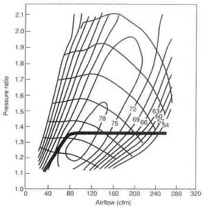
Fig. 17-10. Aerocharger model 101 compressor flow map. The heavy line indicates the path of the boost. Note that at 260 cfm, the line extends out to approximately 50% thermal efficiency. This is too low for an acceptable system.
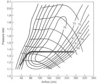
Fig.17-11. Aerocharger model 128 compressor flow map. The same data plotted on this compressor map show a maximum load efficiency dropping from a peak of 76% to a low of 60%. This is 10% great-er than the model 101 at maximum load, and is thus a better choice.
Using the formula for compressor efficiency from Chapter 14, we can derive the temperature rise at maximum efficiency:
![]()
Therefore,
![]()
Inserting the above values,
![]()
Since the size of an
absolute degree is the same as that of a Fahrenheit degree, the rise of 63 at
maximum efficiency added to the ambient temperature of
Temperature rise at maximum load can be derived by multiplying the calculated value of 63 by the ratio of the highest efficiency to the lowest efficiency of the system as previously plotted on the flow map:
![]()
The rise of 79 at
maximum load added to the ambient temperature of
This calculation
predicts a maximum compressor discharge temperature gain of
The value of intercooling can be estimated by a ratio of the absolute temperatures before and after cooling. This ratio represents the relative density change. It is adequate to assume an intercooler efficiency of 85% for preliminary calculations. An 85% efficient intercooler will remove 85% of the heat put in by the compressor. Therefore, using the formula from Chapter 5 for temperature removed, the expected temperature exiting the intercooler will be
![]() F above ambient.
F above ambient.
Using the formula for density change from Chapter 5,
![]()
In view of the high compression ratio (10.2 to 1) of the NSX engine and a charge density gain of 11.9%, the decision to include intercoolers in the system is at easy one.
Refer to earlier in this chapter for the factors to consider in deciding layout.
Turbo position. The Aerocharger gives a freedom of choice not heretofore available in positioning the turbo. The absence of any oil lines to the self-lubricating Aerocharger removes the requirement for either a gravity drain or a sump-pump-aided oil return.
Although the turbocharger is traditionally placed between engine and converter, the selection of turbocharger with the ability to make considerable boost at low exhaust gas flow suggests that they can be placed after the converters. This position still offers a high degree of response yet permits the converters to get exhaust gas beat undiminished from the engine, to facilitate catalyst light-off.
Some attention to a symmetrical turbo position with respect to the exhaust header will require one header pipe to be longer than the other, but this is not of major significance.
Intercooler design. Anticipated power output will dictate the internal flow area of the intercoolers. As discussed in Chapter 5, when pressure loss through
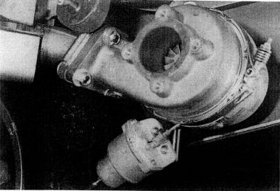
Fig. 17-12. Positioning the right turbo required temporarily hanging it from fasteners on the heat shield directly above it, then making a mock-up of and building the short tube assembly between the converter and the turbine inlet
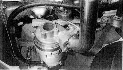
Fig. 17-13. The left turbo hangs from the original rubber tailpipe mount. The turbine inlet pipe originales at the center converter. The fiber hose runs forward, to the valve-cover breather.
the cooler is controlled to an acceptable value, temperature drops will always fall in line, with no other requirement than an adequate supply of ambient air. The suggested value is 6 square inches flow area per 100 bhp. Assuming a desired bhp of 375,
![]()
Using the guidelines
discussed in Chapter 5, the core material with 23 square inches of flow area
will typically be a core with 46 square inches on the core face exposed to the
charge, because about half the face is composed of the air tubes. So a core
with a depth of
A search For space for
a core this size, or two cores half this size, reveals a location aft of the
rear wheels with space for cores of
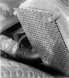
Fig. 17-14. The intercoolers are positioned behind the rear wheels. Heavy mesh screens offer protection from road debris.
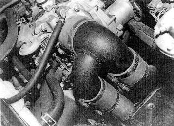
Fig. 17-15. Plumbing from the intercoolers unites in a single inlet to the throttle body. The mechanism attached to the forward aide of the throttle inlet casting in an overboost safety vent value.
Debris thrown by the tires is a problem to be resolved. Heavy screens of stainless wire mesh that will allow airflow but defeat rock flow are adequate to protect the intercoolers from foreign-particle damage.
Exhaust system. The quality and material of the Borla stainless steel muffler were
felt to be consistent with the vehicle's quality. As the turbine exit diameter
is
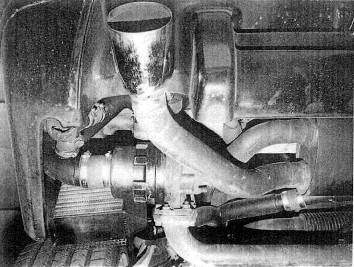
Fig. 17-
Although the exhaust system is quite compact, silencing proved to be adequate, since the turbos themselves function as approximately one-third of the silencing requirement.
Compressor bypass valve. The need for compressor bypass valves to suppress surge noise on lifting off throttle is less necessary with the Aerocharger than with standard turbos. Initial testing showed the noise not entirely suppressed by the Aerocharger; thus, valves were incorporated into the design.
Because bypass valves can offer their own characteristic air venting sound, they were placed at the farthest point in the system from the driver. The available space is directly across the compressor, from outlet to inlet.
The bypass valves are operated by intake manifold vacuum signals. For coherent signals, two dedicated lines were run from the intake manifold to the valves.
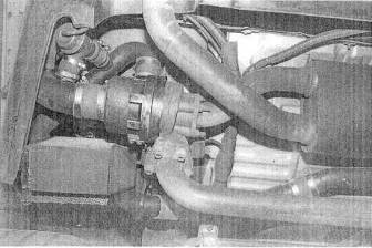
Fig. 17-17. With the compressor discharge tube to the intercooler installed, the bypass valve can be set to vent directly from the discharge tube to the compressor inlet tube.
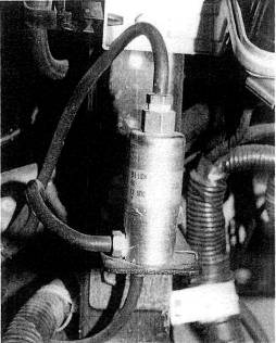
Fig. 17-18. Because the ECU is not programmed for pressure above atmospheric in the intake manifold, a signal block is necessary to keep the MAP sensor from receiving pressure when the engine is under boost.
Material selection is critical only with respect to the hot side of the turbo system. Because the layout will not cause thermally induced expansion, stainless steel can be used for the hot side. Stainless grade 304 was chosen for its combination of high-temperature strength and long-term corrosion resistance. It is also readily weldable with the tig process. Mild steel was used for flanges, which need not be stainless.
Tubing used in the cold-side plumbing is all mandrel-bent, thin-walled mild steel, which is easily welded, internally smooth, and can be finished in a wide variety of processes. The ends of the tubes are soil enough to permit flaring, for better hose retention. All hose connections are of high-temperature, hydrocarbon-proof silicone hose material.
The aluminum intercooler cores are welded to cast 363 aluminum alloy caps. All tabs, mounts, and hose bosses are cut from aluminum 6063-T3 (heat-treated) alloy.
Construction sequence follows the order given in the list of factors to consider earlier in this chapter.
Stainless grade 304
does not require any coatings for long-term durability or appearance. All
aluminum and mild-steel components are subject to corrosion and discoloration
without protective coatings. Chrome plating was not considered, as it is
difficult to keep hose connections from sliding off chromed parts. Powder
coatings satisfy all appearance and durability requirements, with the added
benefit of a wrinkle-texture finish for improved grip on hose connections.
Powder coating of wrinkle black was applied to all parts that do not see
temperatures in excess of
The NSX design offers a series of flanged joints. These are best served by through-bolts, (See earlier discussion.) The turbine outlet requires a stud anchored into the cast iron housing with a mechanical locknut.
All joints must be examined as to the need for a gasket. If a gasket is required, the choice of style and material must be made. The NSX design offered no circumstances where a gasket could be omitted from a bolted joint. Although it is common to omit a gasket between a turbo and an exhaust manifold with machined flat surfaces, the NSX presented no such opportunity.
As discussed in Chapter 10, the sandwich-type gasket is preferable, but it was not available. The second choice, embossed stainless, is included with the Aerocharger.
The testing process has two primary objectives: tuning the details and checking to see if any major errors in the designer's judgment have occurred.
Tuning the air/fuel ratio is clearly the first necessity. Measurements were made with the Horiba meter. This meter has an electrically heated oxygen sensor that conveniently mounts in the exhaust pipe outlet. Initial bench calibration of the fuel pressure regulator was for 82 psi at 5 psi boost. This number did not prove quite adequate, as a fuel pressure of 92-95 psi was required to achieve the desired 13 to 1 air/fuel ratio. The discrepancy comes from the need to run a richer mixture under boost than the normally aspirated engine runs at full throttle. The regulator was therefore adjusted to provide the higher flow rate.
Checks on the air/fuel mixture were also made at 1 and 3 psi boost to assure that the regulator was keeping the mid-range mixtures correct as well. These pressures measured 55 and 70 psi, respectively. The Horiba indicated that these pressures created a progressive change in air/fuel ratio from 15 to 1 down to 12.3 to 1 as boost increased from 1 to 5 psi.
With the confidence thai the air/fuel mixture is in the appropriate range, we were free to test for engine knock. Trust in the ability of the ear to detect detonation did not seem appropriate with an engine as expensive as the NSX's, so a J&S Electronics knock indicator was used as a supplement. Both indicated no knock was present in repeated runs to the redline under maximum boost.
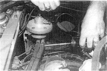
Fig. 17-19. The rising-rate fuel pressure regulator fits easily in the space previously occupied by the air filter box. The regulator has two adjustments. The side adjustment. a needle valve, determines fuel pressure at maximum boost. The spring-loaded center screw sets the point of onset of pressure gain.
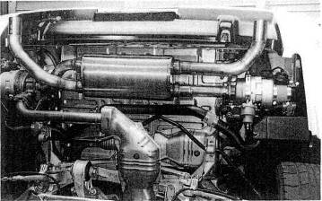
Fig. 17-20. The lower side of the finished assembly.
Testing weather was a hot and sunny 100 August day. The judgment that this was harsher than moat operational conditions suggested that the system would be free of detonation virtually anywhere.
With safety of the system established, testing of adherence to the design objectives tan begin.
Since a graph of efficiency of the compressor plotted versus airflow and boost pressure is always a curve, it is necessary to determine whether our data points are on the upslope or downslope.
Four items of information are necessary: temperature into and out of the turbo compressor, boost pressure, and engine rpm. Measurements must be made at full throttle yet must also be as near steady-state as possible. To do this, we chose 6000 rpm in third gear and 4000 rpm in fourth gear. By dragging the brakes and not permitting the vehicle to accelerate, some reasonable degree of steady state can be achieved. From the gauges, it appears to take 6 to 8 seconds to reach a steady state. Three trials created the data shown in the following table. The pressure ratio and cfm are calculated as shown earlier in this chapter. One should always make note of the ambient temperature.
|
Boost (psi) |
Rpm |
Temperature in (F) |
Temperature out (F) |
Pressure ratio |
Calculated cfm |
|
|
Three trials are barely adequate to establish the best and worst conditions, but this is a field test, not Porsche's research laboratory. The data with asterisks, which are median numbers, will be used for analysis. The process is to calculate what the compressor maps indicate the temperatures ought to be and compare those numbers with the actual measurements.
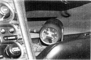
Fig. 17-21. The vacuum/boost gauge is not used frequently and is therefore mounted in
the glove box, where it can be referred to if necessary.
The estimate of
temperature gains at the initial selection of turbo compressors was
Temperature inlet measurements in the above table indicate a 2 temperature rise at the point of air pickup by the filters. With the filters positioned inside the rear fenders, air temperature should be ambient. Possibly the temperature sensor was receiving heat radiated from the exhaust housing, or a convection current (misunderstood airflow) was carrying heat from the turbo toward the temperature sensor. Curious, but insignificant.
The exhaust gas pressure change across the turbines tell us two things: whether turbine size is close to that desired, and the amount of exhaust back pressure created by the muffler and tailpipe.
Turbine inlet pressure is measured by placing a fitting on one of the turbine inlet pipes and attaching a pressure gauge. The expected turbine inlet pressure is usually two to three times greater than the boost pressure generated; therefore, we expected 12 to 18 psi. Surprisingly, 15 psi was the maximum pressure developed before the turbine, with just .5 psi after. Although a slight decrease in inlet pressure would be desirable, it is not enough so to install bigger turbines and produce any less low-speed response. The .5 psi loss through the muffler and exhaust plumbing is entirely satisfactory.
Verifying the value of the intercooler will indicate that temperature drops across the coolers are sufficient and that pressure loss remains below 1 psi at maximum load.
Only one pressure-Iowa check was made at redline rpm: it showed a tick over 1 psi at 7700-7800 rpm, While this was slightly disappointing, the decision was made to keep the intercoolers as Is if heat rejection efficiency exceeded 80%.
Temperature probes placed in the compressor outlet and intercooler outlet will collect the necessary data for intercooler efficiency calculation, including ambient temperature.
Testing was conducted by holding steady-state maximum boost at 4000 rpm in fourth gear. Again. 6 to 8 seconds appeared to be needed to stabilize
temperatures and the response times of the gauges. Four tests were made to collect the data, as shown in the table. Although the results are reasonably consistent, data collection is not always as one wants it to be. The real efficiency is probably dose to the average of the four trials.
Using representative values from the table in the formula for intercooler thermal efficiency from Chapter 5,
The net result of the
intercooling effort is to get the charge temperature to within 12 to
|
Test |
Ambient temperature (F) |
Turbo outlet temperature (F) |
Intercooler outlet temperature (F) |
The four-gas-analyser emissions test was repeated after system installation was complete. No surprises were in store. Hydrocarbons and carbon monoxide showed a slight decrease, all else remaining virtually unchanged. The odd note of air/fuel ratios running about 2% richer at all times was observed. No ready explanation is offered. The conclusion is that the system should not have any difficulty passing the CARB test procedures.
The Varicom VC200 was again the instrument of measurement for post-turbo performance. Six efforts at establishing some degree of consistency gave the following data:
0 to 60; best, 4.4 sec; average, 4.7 sec
l/4-mile time; best, 12.8 sec; average, 13.0 sec
1/4-mile speed; best,
Power: 390 bhp
How difficult is it to install a turbocharger system?
The skill required is comparable to that of overhauling a two-barrel carburetor. The time required is at least twice the kit maker's claim. You may be assured that the lowest time claim will be the least comprehensive turbo kit. It Lakes no time at all net to install a wastegate, for example. Be assured also that the details determine the success of a turbo installation. Anyone can figure out where the exhaust manifold goes, but it takes patience and care to get all the small adjustments made correctly. It is in this respect that the do-it-yourselfer will usually exel in a truly quality job.
Will I need any special tools?
Not likely, although a special tool for torquing the cylinder-head bolts may be required.
What gauging should accompany a turbo?
A vacuum/boost gauge is a virtual necessity. An exhaust gas temperature gauge is a nice addition, particularly on engines with characteristically high exhaust temperatures. Diesel engines are another matter. Their redline is a function of exhaust temperature, and they must have egt gauges.
Will I have to buy anything else to supplement the turbocharger?
Wow, what a loaded question. Every kit maker's system is 'complete.' If the kit is heavily advertised as 'complete,' you had better he prepared to bring along your own wastegate, exhaust system, boost gauge, fuel system, and detonation controls. 'Comprehensive' is the descriptive term you are looking for, not that tired, overworked term ''complete.'
Are chromed steel parts necessary?
Chrome does not rust and is durable. Chrome is a nice touch, provided it is consistent with the OEM components. It is, however, too slippery for hose connections. The general rule is, If it doesn't work well, chrome-plate it.
|
Politica de confidentialitate | Termeni si conditii de utilizare |

Vizualizari: 1058
Importanta: ![]()
Termeni si conditii de utilizare | Contact
© SCRIGROUP 2025 . All rights reserved