| CATEGORII DOCUMENTE |
| Bulgara | Ceha slovaca | Croata | Engleza | Estona | Finlandeza | Franceza |
| Germana | Italiana | Letona | Lituaniana | Maghiara | Olandeza | Poloneza |
| Sarba | Slovena | Spaniola | Suedeza | Turca | Ucraineana |
At first glance, the idea of a modern turbocharged engine and carburetors all in the same package appears to be a contradiction. A closer inspection reveals that it is indeed a contradiction. Rather than Ignore these antique devices, this chapter will attempt to outline the operating principles behind carburetor integration into a turbo system.
The reasons carbs do not completely satisfy the fueling requirements of a turbo engine are basic and clear-cut. Two reasons stand out; the airflow range over which a carb can successfully operate, and the inability of a draw-through carburetor system to function with an intercooler. A carburetor has three items controlling fuel flow: idle jet, main jet, and air corrector jetand, on occasion, power jets. While these controlling factors will allow satisfactory operation over a range of 20 to 25 psi absolute (5 to 10 psi boost), there is little hope for accurate fuel mixture control to satisfy either peak performance or any emission standards, The physical principles of fluid mechanics simply do not allow it.
Two different setups are possible with carbureted turbo systems. With a draw-through type, the carburetor is positioned in front of the turbo, and all the air/fuel mixture flows through the entire system.
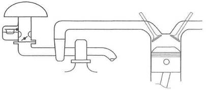
Fig, 8-1. The basic layout of the draw-through carb system
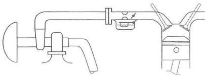
Fig. 8-2. The blow-through carb layout presents a far superior path for the air/fuel mixture, to traverse than does the draw-through setup.
With the blow-through type the layout is reversed, to place the carburetor after the turbo. In the blow-through type, the air/fuel mixture does not flow through the turbo,
The two types have their own areas of merit. The draw-though system is simpler and, because it is a low-pressure system, no change occurs in air density at the carburetor. Further, no compressor bypass valve is required.
That is all that can be said for the draw-through system.
The blow-through system has better throttle response and cold starting, reduced emissions, and permits use of an intercooler.
Weighing the merits, there is virtually no reason to build a draw-through system unless one lives in a year-round hot climate and never intends to produce serious power.
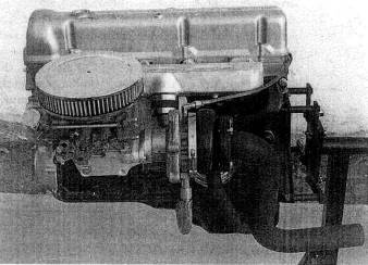
Fig. 8-3. Early carbureted turbos, like this one, generally drew through the carb. These have all been succeeded by the more modern blow-through designs.
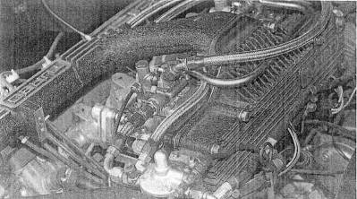
Fig. 8-4. This beautiful hardware was created by Lotus for the Esprit and features two blow-through Dellorto side-draft carbs. Note the fuel pressure regulator at the end of the plenum and its boost-pressure sensing line.
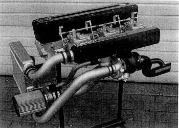
Fig. 8-5. Three Mikuni PH44 carbs feed this Nissan Z car engine. Note the antisurge valve below the plenum and its return vent to the air-filter mount.
The primary concern in the draw-through layout is that the air/fuel mixture be permitted to flow downhill at all times. This condition is not possible due to the compressor inlet scroll, hut no other item should be allowed to serve as a low point. Fuel tends to drop out of the mixture and puddle at low points. Puddling will badly upset the cold idle and low-speed response,
A water jacket added
to warm the carb mount and bottom of the turbo scroll will alleviate cold fuel
puddling. However, the mere thought of purposely adding heat to the intake
system should be considered nothing short of revolting. A further addition of
heat may be required to prevent carburetor icing when operating under boost.
Typically, a correct air/fuel ratio will create about a
Sizing the carb for a draw-through system should take into account the basic cfm capability of the engine without considering the turbo. The reason for this is that cfm ratings of carburetors are based on atmospheric pressure drops only, whereas the turbo can violate these conditions by changing vacuum conditions after the throttle plates. Consider that the only way a carb with atmospheric pressure above the throttle plates can How more air on a given engine is to have lower pressure, created by the turbo, after the throttle plates. In other words, the turbo creates a bigger pressure drop across the carb.
The draw-through carb system has a hidden pitfall in the area of selecting a suitably sized carburetor. This pitfall is created by the odd circumstance that allows one cylinder at a time to breathe through the sum of the carb throats open at that specific time. For example, imagine a dual-throat carb mounted in front of the turbo, all of which is mounted on a four-cylinder engine. Although the carb cfm rating may match the system just fine, we have a situation where-in each cylinder is breathing through the two throats. That equates to putting four dual-throat carbs onto a four-cylinder enginecertainly a situation that would be badly overcarbureted. The disaster comes about from the fact that the one cylinder drawing through two throats yields a very slow air velocity at the carburetor venturi. This sends a weak vacuum signal to the main jet; hence, lousy fuel metering. The situation is somewhat alleviated by having more cylinders, yet the fundamental problem remains. The proper solution to the problem is the selection of a carb with a small primary(s) and vacuum-operated secondaries.
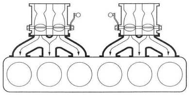
Fig. 8-6. Do not pemit a layout to exist where a single cylinder can be fed by two carb throats simultaneously. This is akin to severe overcarburetion and functions poorly.
Preparing the draw-through carb for turbo use presents no special problems. Clearly. the jetting will need to be developed on an individual basis. Most situations will call Tor somewhat larger main jets, accelerator pump delivery, and idle jets than will the normally aspirated engine of the same size. The float needle assembly will usually require considerable expansion in order to keep up with the newfound fuel flow requirements.
The blow-through system permits an ideal layout for the distribution of fuel to the cylinders. All the classic layouts of carburetor position relative to engine configuration are unaffected by the prospect of blowing pressurized air through the carbs. These layouts worked marvelously in their day as normally aspirated engines and would certainly do so as blow-through turbo applications. Although available space frequently influences the number and type of carbs, one carburetor throat per cylinder should always be the objective. Several design parameters must be met in laying out a blow-through system:
Fuel pressure must be controlled as a function of boost pressure.
All components of the fuel system must withstand the higher Fuel pressures.
A compressor bypass valve is required.
Controlling fuel pressure. The requirement for varying fuel pressure comes about from the fact that the carburetor float bowls will experience a pressure change from roughly atmospheric at idle and cruise to the maximum boost of the turbo. If fuel pressure were a constant 4 psi, say, then when boost pressure exceeded that 4 psi, Fuel would be driven backward into the fuel tank. Obviously, the pressure required to get fuel to enter a float bowl occupied by 15 psi of pressure will require fuel pressure of 18 or 20 psi. This 18 or 20 psi, if held constant at all conditions, might work fine under boost but would badly flood all known carbs at idle or cruise. The answer is a fuel pressure regulator that varies fuel pressure as a function of boost.
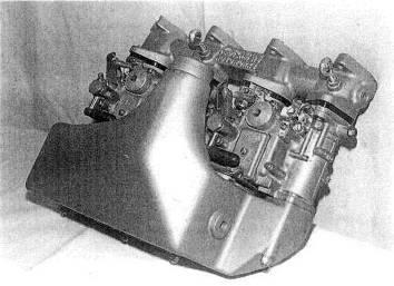
Fig. 8-7. The aftermarket BMW 2002 turbo featured twin blow-through Mikuni/ Solex carbs. This design incorporates a water-based intercooler into the plenum.
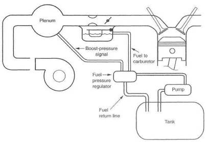
Fig. 8-8. The blow-through system must have a boost-pressure-sensitive fuel pressure regulator
Fuel pump requirements. The need to flow large quantities of fuel while operating under boost is obvious. Fuel pumps, pressure ranges, and flow capacities are discussed in Chapter 7.
Bypass valve. The compressor bypass valve, or antisurge valve, is essential to the smooth running of the blow-through system. The particular situation that requires the presence of the valve is when the throttle is suddenly closed after operating under boost. This is nothing more than the process of shifting gears when driving under boost. The problem comes about when the closed throttle creates manifold vacuum. The idle jet discharge orifice is then in a vacuum condition when the idle jet inlet is still pressurized, via the float bowl, from the turbo, which is still trying to pump air. This pressure difference across the idle jet causes a large discharge of fuel out of the jet, producing a sudden rich condition. When the gear change is accomplished and throttle re-applied, engine response deteriorates, due to the sudden air/fuel ratio change to the rich condition. The situation clears up as soon as the system again achieves a constant boost condition, where pressure is the same on both ends of the idle jet circuit.
The bypass valve is designed to dump the pressure upstream of the throttle when the throttle is closed, quickly bringing the system to a stabilized pressure. The valve does this by using the vacuum signal generated in the intake manifold when the throttle is closed to open a valve that lets the pressure rapidly bleed off.
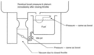
Fig. 8-9. When operating under boost, the entire carb is under pressure. As the. throttle is closed, residual pressure in the float and vacuum below the throttle plate will cause considerable flow through the idle jet, upsetting throttle response, The bypass valve rapidly dissipates the float/plenum pressure.
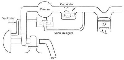
Fig, 8-10. The bypass, or antisurge, valve is necessary in blow-through designs to relieve float-bowl pressure quickly on lifting off the throttle.
Vacuum and pressure distribution. Critical to the successful operation of the blow-through carb system is the source of the signals used to control the wastegate and fuel pressure regulator. This condition arises from the absolute need to control the pressure difference across the carburetor float needle. This pressure difference is the difference between the fuel pressure pushing the fuel into the float bowl and the boost pressure that exists in the float bowl at any given time.
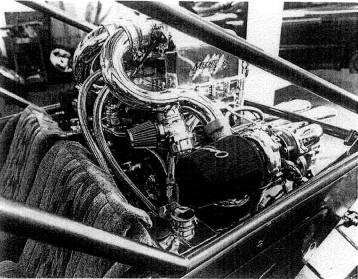
Fig. 8-
This pressure difference must be held constant under all operational conditions. To accomplish this, It is vital that both control signals be taken from the intake plenum prior to the throttle plates. It is best to take the signals from the same location. To illustrate what can happen if this requirement is not met, imagine hooking both signals to the intake manifold alter the throttle plate, This is always the last place to see boost pressure, and it is always the lowest pressure. Pressure losses thru the carb can be as high as 3 or 4 psi. If the wastegate signal then comes from the manifold, the float bowl will see a pressure 3 or 4 psi greater. If fuel pressure is set 5 psi above boost pressure, then the real pressure difference across the float needle will be 1 or 2, certainly not enough to run under boost. If fuel pressure is raised to compensate, the idle setting will be off when the float bowl sees atmospheric pressure. Back at idle, fuel pressure will be 8 or 9 psi, an unstable fuel pressure for a float needle assembly.
Preparing the carburetor. Several aspects of the carburetor need inspection and/or preparation for use in a blow-through application.
The blow-through carb must have a solid float. Should the one you choose to use have a brass-sheet float or other style that could collapse under boost pressure, the float must be replaced with a solid unit. A variety of techniques exist to fill a hollow float with lightweight foam. Some of these come in a liquid and harden after being injected into the float Consult the Yellow Pages, under ad-hesives,
Inspect the carb thoroughly for lead plugs that cap off intersecting drilled passages. These plugs are prone to dislodge with boost pressure. The plug can be retained by staking it in with a sharp-pointed center punch. Set a ring of punches around the plug such that the base metal of the carb body is raised enough to create interference should the plug try to move. Another method of retaining the plugs is simply to cover them with a high-quality epoxy glue. Be mindful of the fact that larger plugs will fail first, as they inherently have a larger force trying to push them out.
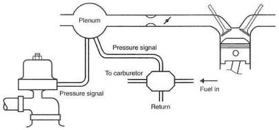
Fig. 8-12. Signals for the wastegate and fuel pressure regulator need to originate at the same point in the system and before the throttle plate.
Inspect ail the gaskets in the carburetor, Any gasket that appears less than up to the task must be improved. It is possible to retain a gasket with a very light coating of Loctite applied to one side only. Under no circumstances should you use a silicone or similar rubbery-style sealer, as you will be finding it in the fuel jets after the first trip around the block. It is especially important to seal all gaskets or other items on the float bowl lid to avoid losing boost-pressure balance across the main jets. If any pressure leaks whatsoever occur from the float bowl, fuel delivery will grow lean on rising boost pressure.
The throttle shafts on the carb will seep fuel under boost if not sealed against pressure. Most seepage will be in the annoying category and will not affect safety or function. Cosmetics dictate that the shafts receive some form of seal. Probably the easiest and most effective method is to offer a pressure barrier that will tend to force the air/fuel mixture back into the carb throat. This can easily be done by bleeding some boost out of the plenum on the face of the carb, down to small fittings placed into the bosses through which the throttle shafts pass.
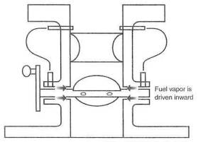
Fig. 8-13. When fuel leakage at the throttle shaft is a problem, boost pressure from above the venturi, which will always he greater than that below the venturi can he channeled to the shaft pivot bores to blow the mixture back into the throat..
Cold-start valves of the fuel-dump style, rather than the air-restrictor type, may need to be pressure balanced against a reverse flow when operating under boost. Should this be a problem, it can be dealt with by creating a cap of sorts over the cold-start valve and bleeding pressure from the plenum into this cap. The cap can be bonded onto the carb with a high-quality epoxy cement.
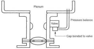
Fig. 8-14. Cold-start valves can commonly leak backward under boost. A pressure balance across the value will solve the problem.
Suitable carbs for blow-through application. Almost any carburetor can be prepared for use
in a blow-through turbo system. It is clear, however, that some carbs present a
serious preparation challenge, while others are just plain easy to use.
Manufacturers like Weber,
Plenum design. The plenum is the component that focuses air for its trip through the carb. Although plenums are simple in concept, a few rules should be observed in plenum design:
Make the volume of the plenum 110-120% of the engine displacement.
Straighten out the airflow before the air corrector jet assemblies. Air swirling around an air corrector prevents the jet from functioning,
Have the shape into the carb throats approach that of an ideal inlet.
Don't blow air directly across a carb throat.
Provide for air bleeds to the float bowls.
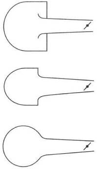
Fig. 8-15. The plenum vent ports to the throttle bores must incorporate a bell-mouthed form approaching an ideal air inlet, shape.
Does an air/fuel mixture have trouble staying atomized through an idling turbo at low ambient temperatures?
Draw-through-carb
turbo systems inherently have a long, devious route for the air/fuel mixture to
travel before reaching the cylinders. If heat is not provided at the carb
mount or near the system's low point, fuel will puddle in the bottom of the
turbo. In practice, carb preheat allows the engine to idle and run smoothly at
low speeds when ambient temperature is less than
Are blow-through carb systems technically and functionally workable?
Yes. For some heavy-hitting evidence, drive a Lotus Turbo Esprit or a Mase-rati Bi-Turbo.
Has the controversy of blow-though versus draw-through carb systems been resolved?
Not only yes, but hell yes. Blow-through starts better, idles better, runs smoother at low speed, and produces quicker throttle response and lower emissions. An intercooler can only be used with a blow-through application. The draw-through system is a dead fish.
|
Politica de confidentialitate | Termeni si conditii de utilizare |

Vizualizari: 5048
Importanta: ![]()
Termeni si conditii de utilizare | Contact
© SCRIGROUP 2025 . All rights reserved