| CATEGORII DOCUMENTE |
| Bulgara | Ceha slovaca | Croata | Engleza | Estona | Finlandeza | Franceza |
| Germana | Italiana | Letona | Lituaniana | Maghiara | Olandeza | Poloneza |
| Sarba | Slovena | Spaniola | Suedeza | Turca | Ucraineana |
3-D MODEL JOB
This job provides 3-axis gouge-free machining of solids and surfaces. It generates roughing, semi-finishing and finishing tool paths. Gouging is prevented even when there are undercut conditions. It can also handle surface gaps and overlaps.
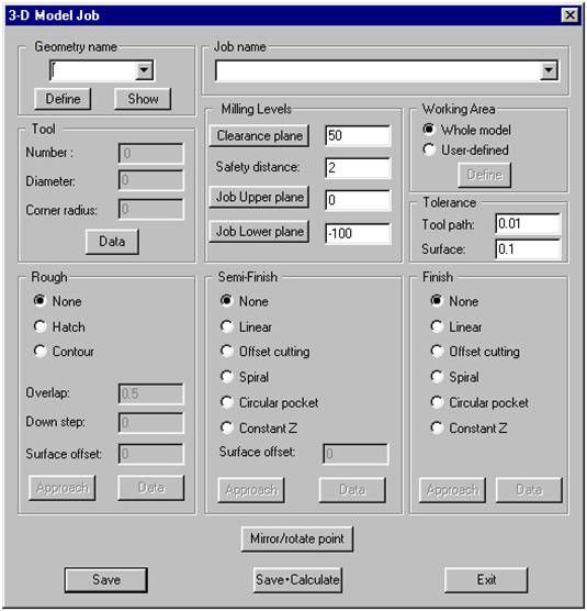
The 3-D MODEL Data-Screen
When you choose the 3-D Model-Job, the 3-D Model data-screen is displayed. You can now either:
Define a new 3-D Model-Job by entering all the technological data in the appropriate fields in the data-screen.
Edit an already-defined 3-D Model-Job by loading it from the disk and then changing any of its fields.
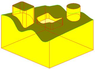
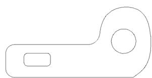
3-D Model job part
Detailed explanation of the fields of the 3-D Model data‑screen:
1 Geometry Name
Enter the name of the geometry to be milled.
1.1 ![]() (The List field)
(The List field)
This field displays a list of the already-defined 3D Model geometries. Choose the geometry to be used for this job from this list.
1.2 Define
This option enables you to define a 3D Model geometry inside the job (instead of defining it using the Geometry command).
Prompts:
Pick an entity or group of entities - Pick the solids and surfaces you want to define. The chosen solids and surfaces will be highlighted. Press the right button of the mouse to display the screen shown below:
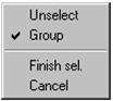
After you have finished selecting entities for the geometry, choose the Finish selog displayed when you press the right mouse button.
The 3-D model geometry dialog box is displayed, enter the name of the geometry in the Name field.
1.3 Show
This option shows you the already-defined 3-D model geometry.
2 Tool
The Tool information field gives you information about the tool used in this job. The Tools Number, Diameter and Corner radius are displayed. When you choose the Data field, the Tool data screen is displayed.
2.1 Tool Number
This field defines the number of the current tool.
2.2 ID Number
This field defines the catalog number of the tool and therefore facilitates the identification of the tool.
2.3 Tool Type
This field enables you to choose the tool type.
2.4 Diameter
This field defines the diameter of the tool.
2.5 Corner Radius
Enter the radius of the corner (between 0 and the tool radius). There are three possibilities:
a. A flat tool is obtained if the corner radius is zero.
b. A ball-nose tool is obtained if the corner radius is equal to the radius of the tool.
Three. If the corner radius is less than the radius of the tool, then a flat tool with a corner
radius is obtained.
2.6 Length
This field defines the length of the tool. In the milling calculations, the system does not use this data; the length of the tool is only output to the G-code file.
2.7 Number of Teeth
This field defines the number of teeth of the tool. This is a very important field since it is used when calculating the feed.
2.8 Description
This field enables you to enter a description of the tool.
2.9 Spin
This field defines the spinning speed of the tool. It defines two spin values:
Spin Rate - Normal spin-rate; used in rough milling.
Spin Finish - Finish spin-rate; used in finish milling.
The spin value can be defined in two types of units, namely S and V. S is the default and it signifies Revolutions per Minute. V signifies Material cutting speed in Meters/Minute in the Metric system or in Feet/Minute in the Inch system; it is calculated according to the following formula:
V = (S * PI * Tool Diameter) / 1000.
2.10 Feed
This field defines the feed rate of the tool. It defines three feed values:
Feed XY - Feed-rate in the XY plane.
Feed Z - Feed-rate in the Z direction.
Feed Finish - Feed-rate used for finish milling.
The feed value can be defined in two types of units, namely: F and Fz. F is the default and it signifies Units per minute. Fz signifies Units per tooth and is calculated according to the following formula:
Fz = F/(Number of Teeth * S)
3 Milling Levels
This group of fields gives you general information about the Planes used in the job.
3.1 Clearance Plane
This is the height to which the tool will rise when moving from one action to the other during the Job. This field gets its default value from the Part Clearance plane; it can be changed, if needed.
3.2 Safety distance
This is the height above the Job upper plane at which the tool will start moving at the specified Z feed-rate. The tool rapids from the Job Clearance plane to this height.
3.3 Job Upper plane
This is the height at which the milling will start for Rough-cutting and Finish Z-level cutting; the Job Upper plane will have no effect on the other cutting strategies. This field gets its default value from the Part Upper plane; it can be changed, if needed.
3.4 Job Lower plane
The tool will not mill lower than the height entered in this field. SOLIDCAM builds a plane at this height; the planes boundary is the bounding box of the model geometry. This field gets its default value from the Part Lower plane; it can be changed, if needed.
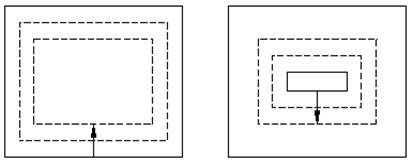
4 Working Area
The Working Area defines the tool path boundary where the milling is performed. It can either automatically include the Whole model or it can be User defined.
4.1 Whole model
In this option, SOLIDCAM automatically calculates the tool path boundary as the bounding box of the model to which a margin, whose width is the tool diameter, is added.
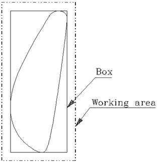
4.2 User-defined
This option enables you to define the Working Area. You are prompted:
Working area - User defined example
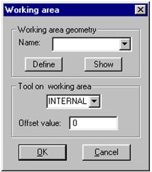
4.2.1 Working area geometry
![]() (The List field)
(The List field)
This field displays a list of the already-defined Working area geometries; you can choose one of these geometries.
Define
This field enables you to define a new Working area.
Show
This field shows you the already-defined Working area.
4.2.2 Tool on Working Area
This field defines the position of the tool relative to the working area. It could be either Internal, External or Middle.
Offset value
This field defines the offset with which the working area is increased or decreased.
5 Tolerance
1 Tool path
The tool path tolerance defines the maximum deviation along the tool path.
2 Surface
The surface tolerance defines the maximum allowed deviation between the original model and the milled part.
6 Approach
This field enables the definition of the approach strategy. The Approach dialog box is displayed, there are two options:
None: A vertical approach is executed.
Angle: User-defined angle for approach.
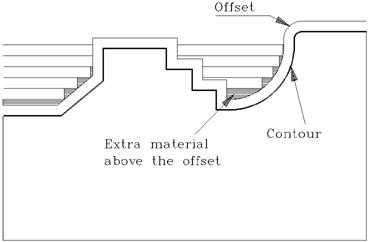
7 Rough
Rough milling is the process of removing the bulk of material surrounding the model; Rough milling removes material from the Job Upper plane to the Job Lower plane. The model is sliced at intervals defined by the down-step; a pocket is generated at each slice whose outside boundary is defined by the Working area. Each pocket is milled either in Hatch or Contour style. The Surface offset for the Rough milling defines the closest distance the tool can get to the model; because of the distance between the slices, a bigger offset is usually left in most places.
7.1 None
No Rough milling is performed.
7.2 Hatch
The tool mills the pocket in a linear pattern.
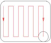
When you choose the Data field, the Rough Hatch parameters box is displayed:
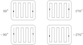
7.2.1 Angle
The Angle field defines the angle for the hatch lines. The value can be between -360 and +360 ; the default value is +90 for vertical lines.
7.2.2 Keep cutting orientation
The cutting orientation is defined by the normal to the hatch. It has two options:
No
Most of the cutting orientation is the default. However the system sometimes changes the cutting orientation by 180 in order to optimize the tool path length.
Yes
The same cutting orientation is maintained.
The default is No.
7.3 Contour
The tool mills the pocket in a round pattern.
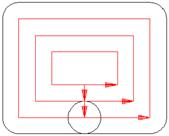
When you choose the Data field, the Rough Contour parameters box is displayed:
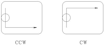
7.3.1 Cutting direction
This field specifies the direction of the tool path; there are two possibilities: Clockwise (CW) or Counterclockwise (CCW).
7.3.2 Start from
This field specifies the start of the tool path. There are two possibilities: Inside or Outside.
Inside
The pocket is milled from the inside to the outside.
Outside
The pocket is milled from the external contour to the inside.
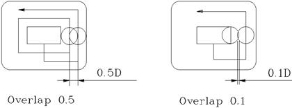
7.4 Overlap
Enter the percent overlap of adjacent tool paths in the milling of pockets at each of the Rough down steps.
7.5 Down step
Enter the depth of the down step between each two successive slices.
Surface offset
The Surface offset value defines the closest distance the tool can get to the model. Only positive values can be entered in this field.
Note:
In order to obtain a uniform offset, semi-finish milling should be executed.
|
Politica de confidentialitate | Termeni si conditii de utilizare |

Vizualizari: 1319
Importanta: ![]()
Termeni si conditii de utilizare | Contact
© SCRIGROUP 2025 . All rights reserved