| CATEGORII DOCUMENTE |
| Bulgara | Ceha slovaca | Croata | Engleza | Estona | Finlandeza | Franceza |
| Germana | Italiana | Letona | Lituaniana | Maghiara | Olandeza | Poloneza |
| Sarba | Slovena | Spaniola | Suedeza | Turca | Ucraineana |
The analysis has been made using standard hand-made calculation methods from Bruhn manuals using F.E.M. model freebodies - interface loads - as applied loads. Each panel, except the ones with the filled circle inside no buckling zones -, has been analyzed extracting on each side the freebody interface loads for all LCs considering all the web shell elements and the interface grids.
![]()
![]()
![]()
![]()
![]()
![]()
![]()
![]()
![]()
![]()
![]()
![]()
![]()
![]()
![]()
![]()
![]()
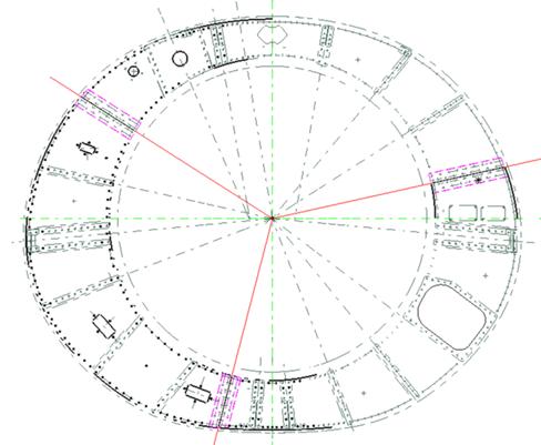
Fig. 2.1 Rear Bulkhead Representation & Panel Identification
Then, averaged tangential forces and normal plane moments on the panel uprights have been considered for compression and bending action, while the averaged upright radial forces and tangential forces on the flanges have been considered for shear action. Although bending, compression and shear effects have been taken into account to calculate the combined action, the web thinness cannot support all those loads, so this will be analyzed for the shear action while the compressive and bending effects will be recalculated to act on the bulkhead flanges, overloading the items compared to the flange FEM internal loads.
.The picture 2.2 shows the generic bulkhead panel, the applied loads, the constraints and used coordinated systems (general cylindrical Xo (tangential direction), Yo (radial direction); local rectangular X, Y).
Fig. 2.2 Panel Loads & Coordinate System Representation
The F.E.M idealization has been placed on top of the previous CAD bulkhead representation giving the following picture result.
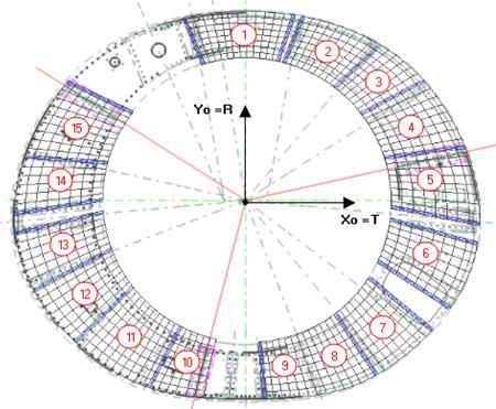
Fig. 2.3 Fem Idealization vs Cad Representation
The following table shows the considered panels CAD geometry:
|
Panel list |
t (mm) |
a (mm) |
b (mm) |
Ax (mm2) |
Ay (mm2) |
Jzx (mm4) |
Jzy (mm4) |
|
Panel.01 | |||||||
|
Panel.02 | |||||||
|
Panel.03 | |||||||
|
Panel.04 | |||||||
|
Panel.05 | |||||||
|
Panel.06 | |||||||
|
Panel.07 | |||||||
|
Panel.08 | |||||||
|
Panel.09 | |||||||
|
Panel.10 | |||||||
|
Panel.11 | |||||||
|
Panel.12 | |||||||
|
Panel.13 | |||||||
|
Panel.14 | |||||||
|
Panel.15 |
Table. 2.4 CAD Geometry
while the following one gives the FEM geometry:
|
Panel list |
t (mm) |
FEM L1 (mm) |
FEM L3 (mm) |
FEM L2 (mm) |
FEM L4 (mm) |
|
Panel.01 | |||||
|
Panel.02 | |||||
|
Panel.03 | |||||
|
Panel.04 | |||||
|
Panel.05 | |||||
|
Panel.06 | |||||
|
Panel.07 | |||||
|
Panel.08 | |||||
|
Panel.09 | |||||
|
Panel.10 | |||||
|
Panel.11 | |||||
|
Panel.12 | |||||
|
Panel.13 | |||||
|
Panel.14 | |||||
|
Panel.15 |
Table. 2.5 FEM Geometry (see fig. 7.2.7.1.2.3)
Since the maximum active temperature on the fwd bulkhead is T = 80C, all panel critical stresses have been calculated for this ambient condition. The critical stresses and the allowable combined formulation outcome, as already explained in par. 7.1.2, from ref. . and ref. .
|
Panel-list |
Kc |
Kb |
KS |
Fc |
Fb |
FS |
|
Panel.01 | ||||||
|
Panel.02 | ||||||
|
Panel.03 | ||||||
|
Panel.04 | ||||||
|
Panel.05 | ||||||
|
Panel.06 | ||||||
|
Panel.07 | ||||||
|
Panel.08 | ||||||
|
Panel.09 | ||||||
|
Panel.10 | ||||||
|
Panel.11 | ||||||
|
Panel.12 | ||||||
|
Panel.13 | ||||||
|
Panel.14 | ||||||
|
Panel.15 |
Table. 2.6 Buckling Coefficients & Allowable Stresses
The following tables group the applied loads & stresses for the most critical shear RF:
|
Panel |
LC |
FX 1* |
FX 2* |
FY 2* |
MZ 2* |
FX |
FX 4* |
FY 4* |
MZ 4* |
|
|
LC_2202800_LL_x_SF | ||||||||||
|
LC_2205300_LL_x_SF | ||||||||||
|
LC_2202700_LL_x_SF | ||||||||||
|
LC_2202700_LL_x_SF | ||||||||||
|
LC_2200900_LL_x_SF | ||||||||||
|
LC_2202700_LL_x_SF |
|
|||||||||
|
|
LC_2202700_LL_x_SF | |||||||||
|
LC_2202700_LL_x_SF | ||||||||||
|
LC_2202700_LL_x_SF | ||||||||||
|
LC_2205600_LL_x_SF | ||||||||||
|
LC_2202700_LL_x_SF | ||||||||||
|
LC_2202700_LL_x_SF | ||||||||||
|
LC_2202700_LL_x_SF | ||||||||||
|
LC_2200900_LL_x_SF | ||||||||||
|
LC_2202600_LL_x_SF |
see fig. 2.2
|
Panel |
LC |
FSX |
FSY |
fxc |
fxb |
fx |
fs |
RS |
|
LC_2202800_LL_x_SF | ||||||||
|
LC_2205300_LL_x_SF | ||||||||
|
LC_2202700_LL_x_SF | ||||||||
|
LC_2202700_LL_x_SF | ||||||||
|
LC_2200900_LL_x_SF | ||||||||
|
LC_2202700_LL_x_SF | ||||||||
|
LC_2202700_LL_x_SF | ||||||||
|
LC_2202700_LL_x_SF | ||||||||
|
LC_2202700_LL_x_SF | ||||||||
|
LC_2205600_LL_x_SF | ||||||||
|
LC_2202700_LL_x_SF | ||||||||
|
LC_2202700_LL_x_SF | ||||||||
|
LC_2202700_LL_x_SF | ||||||||
|
LC_2200900_LL_x_SF | ||||||||
|
LC_2202600_LL_x_SF |
Table 2.7 Applied loads and RFs
where:
Fsx = (Fx1/L1 FEM + Fx3/L3 FEM)/2;
Fsy = (Fx2/L2 FEM + Fx4/L4 FEM)/2;
fxc = (Fx1 + Fx3) /2/Ax;
fxb = (((Mz2 - Mz4) /2)(b/2))(1/Jzx
fx = fxc+ fxb;
fs = (Fsx + Fsy)/2/t;
|
Panel |
LC |
RFs |
fxc1 |
fxb1 |
fx |
fxc2 |
fxb2 |
fxb2 |
|
LC_2202800_LL_x_SF | ||||||||
|
LC_2205300_LL_x_SF | ||||||||
|
LC_2202700_LL_x_SF | ||||||||
|
LC_2202700_LL_x_SF | ||||||||
|
LC_2200900_LL_x_SF | ||||||||
|
LC_2202700_LL_x_SF | ||||||||
|
LC_2202700_LL_x_SF | ||||||||
|
LC_2202700_LL_x_SF | ||||||||
|
LC_2202700_LL_x_SF | ||||||||
|
LC_2205600_LL_x_SF | ||||||||
|
LC_2202700_LL_x_SF | ||||||||
|
LC_2202700_LL_x_SF | ||||||||
|
LC_2202700_LL_x_SF | ||||||||
|
LC_2200900_LL_x_SF | ||||||||
|
LC_2202600_LL_x_SF |
Table 2.8 contd - Applied loads and RFs
where:
RFs = combined formulation for RF with Rs only;
fxc1 = inner flange stress due to compression = fxc/A/2;
fxb1 = inner flange stress due to bending = (Mz2 - Mz4) /2/b;
fx1 = total inner flange stress = fxc1 + fxb1
fxc2 = outer flange stress due to compression = fxc/A/2;
fxb2 = outer flange stress due to bending = - fxb1
fx2 = total outer flange stress = fxc2 + fxb2
The fx1 and fx2 columns will be considered for each load condition - the previous table returns the loads for the most critical shear actions only - along all the flanges and the maximum compressive envelope load will be added to the internal flanges-BAR f.e.m. forces and moments to evaluate the effective post-buckling actions on the items.
Here, the most critical full detailed panel (nr. 8) calculation RFs = 1.10 from Table 2.8 - has been reported:

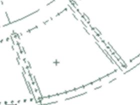
Fig. 2.9 Rear Bulkhead Panel 8 - Zoom
Where, for buckling analysis,:
t = 0.8 mm; a = 235 mm; b = 227 mm;
E80 = 108550 N/mm2; clamped uprights considered;
Kc = 3.73 - ref. . fig. C5.2;
Kb = 21.50 - ref. . fig. C5.14;
Ks = 8.22 - ref. . fig. C5.15;
Fc = Kc E281 (t/b)2 = 3.73 x 108550 x (0.8/227)2 = 5.03 N/mm2;
Fb = Kb E281 (t/b)2 = 21.5 x 108550 x (0.8/227)2 = 28.99 N/mm2;
Fs = Ks E281 (t/b)2 = 8.22 x 108550 x (0.8/227)2 = 11.08 N/mm2;
Fsx = (Fx1/L1 FEM + Fx3/L3 FEM)/2 = - 2221/186.5)/2 = -8.54 N/mm
Fsy = (Fx2/L2 FEM + Fx4/L4 FEM)/2= (-2204/275 -2216/313.2)/2 = -7.58 N/mm;
fxc = (Fy2 + Fy4) /2/Ax = (659 + 562)/2/181.6 = 3.36 N/mm2;
fxb = (((Mz2 - Mz4) /2)(b/2))(1/Jzx) = (((19007+70132)/2)(227/2))(1/779805) = -3.7 N/mm2 ;
fx = fxc+ fxb = 3.36 3.7 = 0.88 N/mm2;
fs = (Fsx + Fsy)/2/t = (-8.54 7.58)/2/0.8 = -10.07 N/mm2;
Rc = fxc/Fc = 0/5.03 = 0.000;
Rb = fxb/Fb = 3.7/28.99 = 0.128;
Rs = fs/Fs = 10.07/11.08 = 0.909;
RF = 2/(Rc + (Rc2 + 4(Rs2 + Rb2)).5) = 1.10 ref. . Par. 6.2.12 eq. 2;
RF Summary
|
Kind of loading S=shear, To=torsion, T=tension, C=compression, VM=VonMises, B=bearing, Be=bending Bck=buckling |
RF = (Allowable/Applied) |
|||||||||
|
ID |
Item |
Mat. |
Load Case |
Kind of load |
Strain Stress Force |
Applied value |
Allowable value |
R.F. |
Remarks |
Page |
|
Str St F |
me Mpa N or N/mm |
me Mpa N or N/mm | ||||||||
|
Web 8 |
Ti-6Al-4V |
LC_2202700 L_x_SF |
Buckling |
St |
T=80C | |||||
Table. 2.10 Minimum RF
|
Politica de confidentialitate | Termeni si conditii de utilizare |

Vizualizari: 924
Importanta: ![]()
Termeni si conditii de utilizare | Contact
© SCRIGROUP 2025 . All rights reserved