| CATEGORII DOCUMENTE |
| Bulgara | Ceha slovaca | Croata | Engleza | Estona | Finlandeza | Franceza |
| Germana | Italiana | Letona | Lituaniana | Maghiara | Olandeza | Poloneza |
| Sarba | Slovena | Spaniola | Suedeza | Turca | Ucraineana |
Active Sub-Woofer and Controller
|
|
|
Introduction
Sub woofers are very popular, with home theatre being one of the driving forces. However, a good sub adds considerably to normal hi-fi program material, and especially so if it is predictable and has good response characteristics.
The majority of sub woofers use a large speaker driver in a large box, with tuning vents and all the difficulties (and vagaries) that conventional operation entails. By conventional, I mean that the speaker and cabinet are operated as a resonant system, using the Thiele-Small parameters to obtain a box which will (if everything works as it should) provide excellent performance.
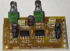
Photo of
Completed Prototype
The principle of Extended Low FrequencyTM(or ELFTM ] is surprisingly uncommon, with one manufacturer that I have found using it in their subs [ ]. I suspect there is one other, but I am not certain that the same method is used - although the principle is the same. Since ELF is trademarked, I will not be using the term in this project, but will refer to my version as Electronically Assisted Subwoofer (EAS). I briefly thought about Electronic Subwoofer Principle (ESP) but decided that would be silly :-)
The basic principles were discovered by Edward Long and Ronald Wickersham (although there is a possibility that others have used similar principles beforehand, there is little available literature), and they both point out that there are some major problems in the reproduction of low bass, highlighting the fact that the bass is the foundation upon which the sound image is created, and that the phase response of ported enclosures can cause 'smearing' of the sound in the time domain. I don't know about 'smearing', but I do know that my prototype provides bass that is deeper and tighter than anything I have heard before. Ported enclosures definitely cause problems with the sound, as the reproduction mechanism relies on two resonant systems, and it takes time for the sound to build up and decay.
Siegfried Linkwitz [ ] developed a circuit that equalises the bottom end of the system, but does not affect the higher frequencies. This is shown and described fully in Project 71, and must be used with a crossover. Although it offers several advantages over the EAS system described here, it is also much more reliant on your detailed knowledge of the loudspeaker driver parameters.
The electronics to perform the necessary processing are easy to build, with the only hard part being a suitably high powered amplifier, and the correct choice of loudspeaker drivers. The cabinet is very easy, since it is small and sealed, so there are no issues with resonance and tuning to worry about.
What? A small, sealed box for a sub-woofer - that can't be right. Well, it is, and the principle is quite different from the conventional approach. When a loudspeaker is installed in a sealed box (or any box, for that matter), it will have a resonant frequency that is higher than in free air. The smaller the box, the higher the resonant frequency will be.
With the EAS approach, the idea is to operate the speaker below resonance, where all the impedance peaks have been left behind in the upper frequencies, leaving a very predictable performance driver to handle the low frequency range. With some experimentation, I determined that a 55 litre box was ideal (it turned out to be 60 litres without the speaker, so with the speaker installed it is about right) for the driver I have, a 4 Ohm, 250W 380mm monster, with a free air resonant frequency of 18Hz. In the small box, this is increased to 63Hz, and this defines the maximum frequency of operation. Resonance probably should have been a little higher, but it manages to sound right, so I shall not worry too much.
Below resonance, a loudspeaker in a sealed box has a response that falls at 12dB / octave, so a means is required to provide an amplifier drive signal that increases at the same rate. A very common circuit in electronics is an integrator, and these are used in many signal processing applications. An integrator has a frequency response that falls at 6dB / octave from DC, extending as far as one wishes. By using two integrators, we obtain a response that falls at 12dB / octave, and by adding resistors, we can cause the response to shelve at any frequency we select. By including capacitors, we can create a high pass filter, so that response to DC is not possible (and nor is it desirable - but more on this later).
|
|
It appears that for reasons that are a complete mystery to me (and others), the ELFTM process is patented. Since the basic theory is public domain, and has been discussed by others [ ], at some length, it is doubtful that a patent challenge would stand up in a court, however I must warn you of this. In theory, the construction of this project is possibly a violation of patent, however for individual use it is impossible to enforce. Commercial production is a different matter, but no-one would do this without my consent anyway (hmmm), naturally having read and understood my disclaimer and copyright notice |
Driver Selection and Hardware
A quick word is warranted here, to allow you to determine if the speaker you have will actually work in a small sealed enclosure. The EAS principle (or Linkwitz transform circuit) will allow any driver to extend to 20 Hz or even lower. A good quick test is to stick the speaker in a box, and drive it to 100W or so at 20 Hz - you should see a lot of cone movement, a few things will rattle, but you shouldn't actually hear a tone. A 'bad' speaker will generate 60 Hz (third harmonic) - if you don't hear anything, the speaker will work in an equalised sub.
If a tone is audible, or the speaker shows any signs of distress (such as the cone breaking up with appropriate awful noises), then the driver cannot be used in this manner. Either find a different driver, or use a vented enclosure.
Before you can build your own EAS box, you will need to select a suitable driver, using the above as a guide. Cone excursion will be very high at the lowest frequencies, so the speaker needs to be capable of high power, good excursion, and of reasonable size (there is no substitute for cone area for moving air at low frequencies). I am using a 380mm (15') driver, but two smaller drivers (say 300mm - 12') can be used, or even a larger number of smaller drivers. I have also had excellent results with a single 300mm driver, which has lower sensitivity (as one would expect) but is perfectly adequate for normal usage.
The test methods I used are applicable to any combination, but in general I suggest either a single large driver or a pair of (say) 300mm units. The next hurdle is the amplifier needed to drive the speaker. This is not trivial. If the selected driver has a sensitivity of 93dB / W @ 1 metre, then you can safely assume that the efficiency will be less than this below resonance, by a factor of maybe 6dB or more. If you are used to driving a sub with 100W, this means that you have just increased the power to 400W - although this is an over-simplification.
If we are to operate the sub from 60Hz (my goal from the beginning), we will increase the power by 12dB for each octave, so if 20W is needed at 60Hz, then at 30Hz this has increased to 320W, and at 15Hz, you will need over 5kW.
Fortunately, the reality is a little different, and 400W or so will be more than sufficient for a fairly powerful system, due mainly to the fact that the energy content in the low bass region is not normally all that great. (Although some program material may have very high energy content, in general this is not the case). The EAS system augments the existing system, which is allowed to roll off naturally - contrast this with the normal case, where a crossover is used to separate the low bass from the main system, so existing speaker capability is lost.
|
|
This method of driving a sub is best suited to systems where the main enclosures are sealed rather than ported. While it will still work with ported systems, the phase response will be unpredictable, and overall performance may not meet your expectations. As an experiment, the port(s) can be blocked. This will not only make the EAS box work better with your main loudspeakers, but will also improve their bass transient response. Make sure that any modification you make is reversible! |
One area where you do need to be very careful is the selection of bass driver and box size. These are critically tied to the characteristics of the selected subwoofer, and should be carefully matched for best performance (and minimum power). If the box is too small, then the resonant frequency will be too high, causing a dramatic decrease in efficiency and a peaking response from the sub. If the box is too large, resonance will be lower than required, and the system will have a response that does meet the 12dB/octave characteristics properly.
It is helpful if you know the -3dB frequency of your main speakers, and multiply by 0.75 to obtain the -6dB frequency. This is the frequency where you will actually cross over from the main speakers to the sub-woofer. The EAS box ideally needs to be tuned so that its resonance is between 1 and 1.4 times that of the main speakers. As part of my experiments, I checked the resonance of my EAS box, and found it to be 63Hz. What surprised me a little was the magnitude of the peak - at just over double the off-resonance impedance. This is very low, and is (presumably) a result of the small box and the fibreglass filling. A standard frequency scan shows a slight rise in output level at resonance, but this may be ignored (the room will have a far more profound effect anyway).
Let's assume that your main speakers are 3dB down at 60Hz - this is the resonant frequency of a sealed box. This means they will be 6dB down at 45Hz. The resonant frequency for the EAS box / loudspeaker combination therefore needs to be between 60Hz and 80Hz to obtain a good match. You will either need to experiment with actual boxes, or use a speaker box design program (BassBox, BoxPlot, etc.) - or just build it and have a listen.
There seems to be a fair bit of flexibility in the system, so it is unlikely that the unit you build will be completely unsuited - unless it has resonance at 60Hz and your main speakers roll off above 100Hz, for example. If you make the box a little too large, it is easy to reduce the volume by adding some suitable packing. If it is too small, this will be slightly more difficult :-)
The box I built is made from 25mm (1') MDF (Medium Density Fibreboard), and packed with fibreglass. Apart from the fact that it is very heavy (which is a good thing, because it wants to walk with low frequencies), the cabinet is acoustically dead, with no resonances in the low frequencies at all (completely unlike my house and furniture, dammit !). The woofer is recessed into the baffle, and sealed with weather sealing foam. When attaching the speaker, do NOT use wood screws, or any other screw into the MDF. I used 'Tee' nuts. I have no idea what they are called elsewhere in the world, but they look like this

Tee Nut
The centre is tapped, and accepts a metal thread screw, and the little spikes mean that you just have to drill a hole, and hammer in the Tee nut. If you use a screw through the hole and screwed lightly into the Tee nut, you can hold it in place as you bash away at it, and can also see that it is straight when you are done. Just make sure that the end of the screw doesn't stick out the end, or you will never remove it again after the hammering! I suggest that you lock the tee nut into place with some construction adhesive (don't get any in the threaded section) so they don't fall out while you are installing the speaker.
The EAS Controller
The controller is quite (actually very) simple, and the circuit is shown in Figure 1. An input buffer ensures that the input impedance of the source does not affect the integrator performance, and allows summing of left and right channels without any crosstalk. The output provides a phase reversal switch, so that the sub can be properly phased to the rest of the system. If the mid-bass disappears as you advance the level control, then the phase is wrong, so just switch to the opposite position.
Figure 1
- The Original EAS Filter / Controller
It turns out that the controller can be simplified, but there really is no point. While the dual pot seemed like a good idea when I built my unit, it actually only changes the gain. Now, having experimented some more, this is a very good thing, since it means that the level through the controller can be set to make sure that there is no distortion - there can be a huge amount of gain at low frequencies, and if the gain is too high, distortion is assured!
The integrators (U1B and U2A) include shelving resistors (R6 and R9), and the capacitor / resistor networks (C1-R4, C3-R7) ensure that signals below 20Hz are attenuated. If you don't want to go that low, then the value of the caps (or the resistors R4 & R7) can be reduced. I used 4.7uF caps, and these are non-polarised electrolytics - a high value was needed to keep the impedance low to the integrators. I originally included the dual pot (VR1) to allow the upper frequency rolloff to be set - however it does no such thing (as described above). The final output level is set with VR2, which may be left out if your power amp has a level control.
It is OK to substitute different opamps, but there is little reason to do so. Any substitution device should be a FET input opamp, or DC offset may be a problem. Do not be tempted to use a DC coupled amp. If the one you are planning to use is DC coupled, the input should be isolated with a capacitor. Choose a value to give a -3dB frequency of about 10Hz, as this will have little effect on the low frequency response, but will help to attenuate the subsonic frequencies.
The unity gain range (using a 20k pot as shown) is from 53Hz to 159Hz. This should be sufficient for most systems, but if desired, the resistors (R5 and R8) can be increased in value to 22k, or you can select a larger value pot. Using 22k resistors and the 20k pot will give a range from 36Hz to 72Hz.
|
|
The unity gain frequency is important in only one respect - it will determine the internal gain of the system, and needs to be set based on the input signal level. If the unity gain frequency is set to (say) 100Hz and there is a 1V RMS input, then a 1V RMS input at 20Hz will severely clip the integrators. I suggest that VR1 should be internal, and set when you know the signal level you will be using - this is determined by the input sensitivity of your power amplifier(s) used on the main system. It is probably easier to experiment a little than try to measure everything. |
To allow lower frequencies, you can increase the 100k shelving resistors (R6 and R9) to 220k, and increase the high pass capacitors (4.7uF) with 10uF (or R4 & R7 may be increased - a maximum of 4.7k is recommended). This will give a turnover frequency of around 8Hz, but expect to use a lot more power, as there will likely be significant sub-sonic energy that will create large cone excursions with no audible benefit.
The input must be a normal full range (or for a biamped system, the complete low frequency signal). Do not use a crossover or other filter before the EAS controller. For final adjustment, and to integrate the system into your listening room, I recommend the Project 84 constant-Q equaliser. The end result using this is extraordinarily good - I have flat in-room response to 20Hz!
For the power supply, use the one in Project 05, or anything else will provide +/-15V at a few milliamps. My supply is not even regulated, and the entire system is as close to noiseless as you will hear (or not hear). Construction is not critical - I built mine on a piece of Veroboard (perforated prototype board), and managed to fit everything (including the power supply rectifier and filter) on a piece about 100 x 40 millimetres with room to spare.
The EAS system is surprisingly easy to set up with no instrumentation. Of course if you have an SPL meter and oscillator you can also verify the settings with measurements. Remember that the room acoustics will play havoc with the results, so unless you want to drag the whole system outdoors, setting by ear might be the easiest. Even if you did get it exactly right in an anechoic environment, this would change completely once it was in your listening room anyway.
It takes a little experimentation to get right, but is surprisingly easy to do. When properly set, a test track (or bass guitar) should be smooth from the highest bass note to the lowest, with no gross peaks or dips. Some are inevitable because of room resonances and the like, but you will find a setting that just sounds 'right' with little difficulty.
Power Amplifier
I have had many requests for a high power amplifier (the 400W unit I am using was a kit - on special - so I couldn't pass it up :-) The easiest is to use the subwoofer amp (Project 68) which is designed specifically for subwoofers.
Now, if you wanted a really powerful sub, use two 300mm (12') woofers, with one 250W amp per speaker. A system such as this would be excellent, especially since the effective cone area is greater than the 380mm woofer I am using. A typical 300mm speaker has a cone area of about 0.05 m versus 0.085 m for a 380mm unit, so two 300mm speakers will have a total effective cone area of 0.1 m. You could go all the way, with a 300mm driver on each face of a cube, with a 250W amp for each. 1500W of low bass should do the job, especially with a cone area of 0.3 m.
This idea is not as silly as it sounds. With six 200mm (8') drivers, you would get a cone area of nearly 0.13 m (about the same as a single 450mm (18') driver), and the box would still only be quite small at about 60 litres (my guess). There is a lot of scope for experimentation, with far less chance of a box being completely useless than with conventional ported designs.
Had the driver I am using not been on special, I probably would have used a pair of 300mm drivers for my own sub. As you may have guessed, I wanted to keep the cost of this down to a minimum. I even managed to get the MDF for AU$15 for the lot - as offcuts. The paint for the box cost more than that !
You must accept that for this project to work, you will need a bigger amp than you might have done otherwise. On the positive side, you will get performance that exceeds that of most subs - mine appears to give almost flat response down to less than 20Hz, except I can't actually hear it. My sound level meter can, and it confirms that the response is there. There is rolloff below 15Hz, but I suspect that is my meter, rather than the woofer, since the dual integrator was still working. This was before I built the unit properly, and I allowed the test circuit to go down to 1.5Hz - this caused some excessive cone excursions, to say the least !
Performance Of My Prototype
I measured 80dB SPL at 1 metre in my
workshop (sub-woofer perched on a stool in more or less the centre of the
space) with at 25Hz and 70W. This improved dramatically when the unit was
installed in the listening room, but as I said earlier, there is generally not
a lot recorded below around 35Hz. The longest pipe on the organ is about 16Hz,
but I think it is not often used (they actually stopped the pipe in the
A couple of orchestral recordings revealed traffic (or perhaps underground railway) rumble that I was completely unaware of before (however this was before it was set correctly, and the bass was a tad louder than needed). Once set up properly, its presence is very unobtrusive - except I now have about one and a half octaves of additional bottom end.
I eventually decided on a 20Hz minimum frequency (-3dB), and this is reflected in the component values shown in Figure 1. The actual roll-over frequency is 16.5Hz, after which the output is attenuated at about 12dB / octave (see Figure 2). Without the rolloff capacitors, the gain would be 20dB at 20Hz. Unity gain frequencies are about 4Hz and 63Hz with the pot 20k centred.
Figure 2
- Frequency Response of EAS Controller
Some Australian readers may recognise the woofer brand in the photo (Figure 3) of my completed unit. The compact size of the box can be seen from the fact that there is very little spacing around the speaker itself, and most of what is there is the top and sides - I used 25mm MDF, so it makes the outside of the box quite a bit bigger than the inside. Outside dimensions are 470W x 450H x 410D (18 1/2'W x 17 1/2'H x 16'D), which gives a capacity of 60 litres (about 2.1 ft - excluding the internal space occupied by the speaker. I think you would agree that this is a small box indeed for a 380mm loudspeaker that performs down to 15Hz.
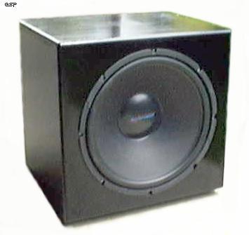
Figure 3
- Photo of Completed EAS Cabinet
Overall, I would have to say that I doubt that any conventional design would be as compact, or would have such clarity and solidarity. Being a sealed box, there is none of the 'waffle' that ported designs often give, and the speaker is protected against excessive excursion by the air pressure in the box itself (below the cutoff frequency, anyway).
The bottom end in my system is now staggering. It is rock solid, and absolutely thunders when called upon. The 400W amp is more than sufficient for the job, considering it has to keep up with a biamped main system capable of very high SPL (up to 120dB at my listening position). In fact a quick test indicates that 200W would have been enough (but better to have it and not need it than need it and not have it).
The fact that the EAS design augments the existing speakers rather than taking over from them completely with a crossover goes a long way towards ensuring the power requirements do not get out of hand. As an added benefit, I have found that I get the same aural sensation at much lower SPLs - I can listen quite happily at 90dB, but it sounds much louder. I can even hear the phone ring while listening now !
All in all, I feel it is unlikely that anything other than an isobaric enclosure could give the same performance for a box size even close to the EAS box, and even then would be limited to about 35Hz. Added to this is the rather unpredictable combined response of the main speakers and the sub, which is not an issue with this design. With an EAS system, more power is needed than a conventional design, but for many people, power is much cheaper than space.
Given the performance, I would never consider a conventional sub again, except for the isobaric I have in my car - that only gets down to 40Hz (-3dB), but is acceptable considering the listening environment. The only other sub that takes my fancy is a dipole (i.e. open backed) arrangement [ ], but I'm afraid that will have to wait for a while now - I have my EAS system, and am very happy with it.
|
Politica de confidentialitate | Termeni si conditii de utilizare |

Vizualizari: 1497
Importanta: ![]()
Termeni si conditii de utilizare | Contact
© SCRIGROUP 2025 . All rights reserved