| CATEGORII DOCUMENTE |
| Bulgara | Ceha slovaca | Croata | Engleza | Estona | Finlandeza | Franceza |
| Germana | Italiana | Letona | Lituaniana | Maghiara | Olandeza | Poloneza |
| Sarba | Slovena | Spaniola | Suedeza | Turca | Ucraineana |
DOCUMENTE SIMILARE |
|
TERMENI importanti pentru acest document |
|
| : | |
PIC Microcontrollers
Introduction
Examples given in this chapter will show you how to connect the PIC microcontroller with other peripheral components or devices when developing your own microcontroller system. Each example contains detailed description of hardware with electrical outline and comments on the program. All programs can be taken directly from the 'MikroElektronika' Internet presentation.
1 Supplying the microcontroller
Generally speaking, the correct voltage supply is of utmost
importance for the proper functioning of the microcontroller system. It can
easily be compared to a man breathing in the air. It is more likely that a man
who is breathing in fresh air will live longer than a man who's living in a
polluted environment.
For a proper function of any microcontroller, it is necessary to provide a
stable source of supply, a sure reset when you turn it on and an oscillator.
According to technical specifications by the manufacturer of PIC
microcontroller, supply voltage should move between 2.0V to 6.0V in all
versions. The simplest solution to the source of supply is using the voltage
stabilizer LM7805 which gives stable +5V on its output. One such source is
shown in the picture below.
In order to function properly, or in order to have stable 5V at the output (pin 3), input voltage on pin 1 of LM7805 should be between 7V through 24V. Depending on current consumption of device we will use the appropriate type of voltage stabilizer LM7805. There are several versions of LM7805. For current consumption of up to 1A we should use the version in TO-220 case with the capability of additional cooling. If the total consumption is 50mA, we can use 78L05 (stabilizer version in small TO - 92 packaging for current of up to 100mA).
2 LED diodes
LEDs are surely one of the most commonly used elements in
electronics. LED is an abbreviation for 'Light Emitting Diode'. When choosing a
LED, several parameters should be looked at: diameter, which is usually 3 or 5
mm (millimeters), working current which is usually about 10mA (It can be as low
as 2mA for LEDs with high efficiency - high light output), and color of course,
which can be red or green though there are also orange, blue, yellow.
LEDs must be connected around the correct way, in order to emit light and the
current-limiting resistor must be the correct value so that the LED is not
damaged or burn out (overheated). The positive of the supply is taken to
the anode, and the cathode goes to the negative or ground of the project
(circuit). In order to identify each lead, the cathode is the shorter lead and
the LED 'bulb' usually has a cut or 'flat' on the cathode
side. Diodes will emit light only if current is flowing from anode to cathode.
Otherwise, its PN junction is reverse biased and current won't flow. In order
to connect a LED correctly, a resistor must be added in series that to limit
the amount of current through the diode, so that it does not burn out. The
value of the resistor is determined by the amount of current you want to flow
through the LED. Maximum current flow trough LED was defined by manufacturer.
|
To determine the value of the dropper-resistor, we need to know the value of the supply voltage. From this we subtract the characteristic voltage drop of a LED. This value will range from 1.2v to 1.6v depending on the color of the LED. The answer is the value of Ur. Using this value and the current we want to flow through the LED (0.002A to 0.01A) we can work out the value of the resistor from the formula R=Ur/I. |
|
LEDs are connected to a microcontroller in two ways. One is to switch them on with logic zero, and other to switch them on with logic one. The first is called NEGATIVE logic and the other is called POSITIVE logic. The next diagram shows how to connect POSITIVE logic. Since POSITIVE logic provides a voltage of +5V to the diode and dropper resistor, it will emit light each time a pin of port B is provided with a logic 1. The other way is to connect all anodes to +5V and to deliver logical zero to cathodes.
Connecting LED diodes to PORTB microcontroller
The following example initializes port B as output and alternately switches on and off LED diodes every 0.5sec. For pause we used macro pausems, which is defined in the file mikroel84.inc.
3 Push buttons
Buttons are mechanical devices used to execute a break or make connection between two points. They come in different sizes and with different purposes. Buttons that are used here are also called 'dip-buttons'. They are soldered directly onto a printed board and are common in electronics. They have four pins (two for each contact) which give them mechanical stability.
Example of connecting buttons to microcontroller pins
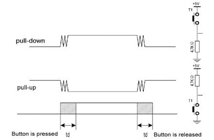
Button function is simple. When we push a button, two contacts are joined together and connection is made. Still, it isn't all that simple. The problem lies in the nature of voltage as an electrical dimension, and in the imperfection of mechanical contacts. That is to say, before contact is made or cut off, there is a short time period when vibration (oscillation) can occur as a result of unevenness of mechanical contacts, or as a result of the different speed in pushing a button (this depends on person who pushes the button). The term given to this phenomena is called SWITCH (CONTACT) DEBOUNCE. If this is overlooked when program is written, an error can occur, or the program can produce more than one output pulse for a single button push. In order to avoid this, we can introduce a small delay when we detect the closing of a contact. This will ensure that the push of a button is interpreted as a single pulse. The debounce delay is produced in software and the length of the delay depends on the button, and the purpose of the button. The problem can be partially solved by adding a capacitor across the button, but a well-designed program is a much-better answer. The program can be adjusted until false detection is completely eliminated. Image below shows what actually happens when button is pushed.
As buttons are very common element in electronics, it would be smart to have a macro for detecting the button is pushed. Macro will be called button. Button has several parameters that deserve additional explanation.
button macro port, pin, hilo, label
Port is a microcontroller's port to which a button is connected. In case
of a PIC16F84 microcontroller, it can be PORTA or PORTB.
Pin is port's pin to which the button is connected.
HiLo can be '0' or '1' which represents the state when the button is pushed.
Label is a destination address for jump to a service subprogram which
will handle the event (button pushed).
Example 1:
button PORTA, 3, 1, Button1
Button T1 is connected to pin RA3 and to the mass across a pull-down resistor, so it generates logical one upon push. When the button is released, program jumps to the label Button1.
Example 2:
button PORTA, 2, 0, Button2
Button T1 is connected to pin RA1 and to the mass across a pull-up resistor, so it generates logical zero upon push. When the button is released, program jumps to the label Button2.
The following example illustrates use of macro button in a program. Buttons are connected to the supply across pull-up resistors and connect to the mass when pushed. Variable cnt is displayed on port B LEDs; cnt is incremented by pushing the button RA0, and is decremented by pushing the button RA1.
It is important to note that this kind of debouncing has certain drawbacks, mainly concerning the idle periods of microcontroller. Namely, microcontroller is in the state of waiting from the moment the button is pushed until it is released, which can be a very long time period in certain applications. if you want the program to be attending to a number of things at the same time, different approach should be used from the start. Solution is to use the interrupt routine for each push of a button, which will occur periodically with pause adequate to compensate for repeated pushes of button.
The idea is simple. Every 10ms, button state will be checked upon and compared to the previous input state. This comparison can detect rising or falling edge of the signal. In case that states are same, there were apparently no changes. In case of change from 0 to a 1, rising edge occurred. If succeeding 3 or 4 checks yield the same result (logical one), we can be positive that the button is pushed.
4 Optocouplers
Optocouplers were discovered right after photo-transistors (like any other transistor, except it is stimulated by light), by combining a LED and photo-transistor in the same case. The purpose of an optocoupler is to separate two parts of a circuit.
This is done for a number of reasons:
Optocouplers can be used as either input or output devices.
They can have additional functions such as intensification of a signal or
Schmitt triggering (the output of a Schmitt trigger is either 0 or 1 - it
changes slow rising and falling waveforms into definite low or high values).
Optocouplers come as a single unit or in groups of two or more in one casing.
Each optocoupler needs two supplies in order to function. They can be used with
one supply, but the voltage isolation feature, which is their primary purpose,
is lost.
4.1 Optocoupler on an input line
The way it works is simple: when a signal arrives, the LED within the optocoupler is turned on, and it illuminates the base of a photo-transistor within the same case. When the transistor is activated, the voltage between collector and emitter falls to 0.7V or less and the microcontroller sees this as a logic zero on its RA4 pin.
The example below is a simplified model of a counter, element commonly utilized in industry (it is used for counting products on a production line, determining motor speed, counting the number of revolutions of an axis, etc). We will have sensor set off the LED every time axis makes a full revolution. LED in turn will 'send' a signal by means of photo-transistor to a microcontroller input RA4 (TOCKI). As prescaler is set to 1:2 in this example, every second signal will increment TMR0. Current status of the counter is displayed on PORTB LEDs.
Example of optocoupler on an input line
4.2 Optocoupler on an output line
An Optocoupler can be also used to separate the output signals. If optocoupler LED is connected to microcontroller pin, logical zero on pin will activate optocoupler LED, thus activating the transistor. This will consequently switch on LED in the part of device working on 12V. Layout of this connection is shown below.
Example of optocoupler on output line
The program for this example is simple. By delivering a logical one to the third pin of port A, the transistor will be activated in the optocoupler, switching on the LED in the part of device working on 12V.
5 Relay
The relay is an electromechanical device, which transforms an electrical signal into mechanical movement. It consists of a coil of insulated wire on a metal core, and a metal armature with one or more contacts. When a supply voltage was delivered to the coil, current would flow and a magnetic field would be produced that moves the armature to close one set of contacts and/or open another set. When power is removed from the relay, the magnetic flux in the coil collapses and produces a fairly high voltage in the opposite direction. This voltage can damage the driver transistor and thus a reverse-biased diode is connected across the coil to 'short-out' the spike when it occurs.
Connecting a relay to the microcontroller via transistor
Since microcontroller cannot provide sufficient supply for a relay coil
(approx. 100+mA is required; microcontroller pin can provide up to 25mA), a
transistor is used for adjustment purposes, its collector circuit containing
the relay coil. When a logical one is delivered to transistor base, transistor
activates the relay, which then, using its contacts, connects other elements in
the circuit. Purpose of the resistor at the transistor base is to keep a
logical zero on base to prevent the relay from activating by mistake. This
ensures that only a clean logical one on RA3 activates the relay.
Connecting the optocoupler and relay to a microcontroller
A relay can also be activated via an optocoupler which at the same time amplifies the current related to the output of the microcontroller and provides a high degree of isolation. High current optocouplers usually contain a 'Darlington' output transistor to provide high output current.
Connecting via an optocoupler is recommended especially for microcontroller applications, where relays are used fro starting high power load, such as motors or heaters, whose voltage instability can put the microcontroller at risk. In our example, when LED is activated on some of the output port pins, the relay is started. Below is the program needed to activate the relay, and includes some of the already discussed macros.
6 Generating sound
In microcontroller systems, beeper is used for indicating certain occurrences, such as push of a button or an error. To have the beeper started, it needs to be delivered a string in binary code - in this way, you can create sounds according to your needs. Connecting the beeper is fairly simple: one pin is connected to the mass, and the other to the microcontroller pin through a capacitor, as shown on the following image.
As with a button, you can employ a macro that will deliver a
BEEP ROUTINE into a program when needed. Macro BEEP has two arguments:
BEEP macro freq , duration:
freq: frequency of the sound. The higher number produces higher
frequency
duration: sound duration. Higher the number, longer the sound.
Example 1: BEEP 0xFF, 0x02
The output has the highest frequency and duration at 2 cycles per 65.3mS which
gives 130.6 mS
Example2: BEEP 0x90, 0x05
The output has a frequency of 0x90 and duration of 5 cycles per 65.3mS. It is
best to determine these macro parameters through experimentation and select the
sound that best suits the application.
The following is the BEEP Macro listing:
The following example shows the use of a macro in a program. The program produces two melodies which are obtained by pressing T1 or T2. Some of the previously discussed macros are included in the program.
7 Shift registers
There are two types of shift registers: input and output. Input shift registers receive data in parallel, through 8 lines and then send it serially through two lines to a microcontroller. Output shift registers work in the opposite direction; they receive serial data and on a 'latch' line signal, they turn it into parallel data. Shift registers are generally used to expand the number of input-output lines of a microcontroller. They are not so much in use any more though, because most modern microcontrollers have a large number of pins. However, their use with microcontrollers such as PIC16F84 is very important.
1 Input shift register 74HC597
Input shift registers transform parallel data into serial data and transfers it to a microcontroller. Their working is quite simple. There are four lines for the transfer of data: Clock, Latch, Load and Data. Data is first read from the input pins by an internal register through a 'latch' signal. Then, with a 'load' signal, data is transferred from the input latch register to the shift register, and from there it is serially transferred to a microcontroller via 'data' and 'clock' lines.
An outline of the connection of the shift register 74HC597 to a micro, is shown below.

In order to simplify the main program, a macro can be used for
the input shift register. Macro HC597 has two parameters:
HC597 macro Var, Var1
Var variable where data from shift register input pins is transferred
Var1 loop counter
Example: HC597 data, counter
Data from the input pins of the shift register is stored in data
variable. Timer/counter variable is used as a loop counter.
Macro listing:
Example of how to use the HC597 macro is given in the following program. Program receives data from a parallel input of the shift register and moves it serially into the RX variable of the microcontroller. LEDs connected to port B will indicate the result of the data input.
2 Output shift register
Output shift registers transform serial data into parallel data. On every rising edge of the clock, the shift register reads the value from data line, stores it in temporary register, and then repeats this cycle 8 times. On a signal from 'latch' line, data is copied from the shift register to input register, thus data is transformed from serial into parallel data.
An outline of the 74HC595 shift register connections is shown on the diagram below:
Macro used in this example can be found in hc595.inc file, and
is called HC595.
Macro HC595 has two parameters:
HC595 macro Var, Var1
Var variable whose contents is transferred to outputs of shift register.
Var1 loop counter
Example: HC595 Data, counter
The data we want to transfer is stored in data variable, and counter variable
is used as a loop counter.
An example of how to use the HC595 macro is given in the following program. Data from variable TX is serially transferred to shift register. LEDs connected to the parallel output of the shift register will indicate the state of the lines. In this example value 0xCB (1100 1011) is sent so that the seventh, sixth, third, first, and zero LEDs are illuminated.
8 Seven-Segment Display (multiplexing)
The segments in a 7-segment display are arranged to form a single digit from 0 to F as shown in the animation:
![]()
We can display a multi-digit number by connecting additional displays. Even though LCD displays are more comfortable to work with, 7-segment displays are still standard in the industry. This is due to their temperature robustness, visibility and wide viewing angle. Segments are marked with non-capital letters: a, b, c, d, e, f, g and dp, where dp is the decimal point. The 8 LEDs inside each display can be arranged with a common cathode or common anode. With a common cathode display, the common cathode must be connected to the 0V rail and the LEDs are turned on with a logic one. Common anode displays must have the common anode connected to the +5V rail. The segments are turned on with a logic zero. The size of a display is measured in millimeters, the height of the digit itself (not the housing, but the digit!). Displays are available with a digit height of 7,10, 13.5, 20, or 25 millimeters. They come in different colors, including: red, orange, and green.
The simplest way to drive a display is via a display driver. These are available for up to 4 displays. Alternatively displays can be driven by a microcontroller and if more than one display is required, the method of driving them is called 'multiplexing.'
The main difference between the two methods is the number of 'drive lines.' A special driver may need only a single 'clock' line and the driver chip will access all the segments and increment the display. If a single display is to be driven from a microcontroller, 7 lines will be needed plus one for the decimal point. For each additional display, only one extra line is needed. To produce a 4, 5 or 6 digit display, all the 7-segment displays are connected in parallel. The common line (the common-cathode line) is taken out separately and this line is taken low for a short period of time to turn on the display. Each display is turned on at a rate above 100 times per second, and it will appear that all the displays are turned on at the same time. As each display is turned on, the appropriate information must be delivered to it so that it will give the correct reading. Up to 6 displays can be accessed like this without the brightness of each display being affected. Each display is turned on very hard for one-sixth the time and the POV (persistence of vision) of our eye thinks the display is turned on the whole time. Therefore, the program has to ensure the proper timing, else the unpleasant blinking of display will occur.
Connecting a microcontroller to 7-segment displays in multiplex mode
Program '7seg.asm' displays decimal value of a number stored in variable D.
Example:
|
movlw .21 | |
|
movlw D |
; number 21 will be printed on 7seg display |
Displaying digits is carried out in multiplex mode which means that the microcontroller alternately prints ones digit and tens digit. TMR0 interrupt serves for generating a time period, so that the program enters the interrupt routine every 5ms and performs multiplexing. In the interrupt routine, first step is deciding which segment should be turned on. In case that the tens digit was previously on, it should be turned off, set the mask for printing the ones digit on 7seg display which lasts 5ms, i.e. until the next interrupt.
For extracting the ones digit and the tens digit, macro digbyte is used. It stores the hundreds digit, the tens digit, and the ones digit into variables Dig1, Dig2, and Dig3. In our case, upon macro execution, Dig1 will equal 0, Dig2 will equal 2, and Dig3 will equal 1.
Realization of the macro is given in the following listing:
The following example shows the use of the macro in a program. Program prints a specified 2-digit number on a 7seg display in multiplex mode.
9 LCD Display
|
More microcontroller devices are using 'smart LCD' displays to output visual information. The following discussion covers the connection of a Hitachi LCD display to a PIC microcontroller. LCD displays designed around Hitachi's LCD HD44780 module, are inexpensive, easy to use, and it is even possible to produce a readout using the 8 x 80 pixels of the display. Hitachi LCD displays have a standard ASCII set of characters plus Japanese, Greek and mathematical symbols. |
|
|
A 16x2 line Hitachi HD44780 display |
For a 8-bit data bus, the display requires a +5V supply plus
11 I/O lines. For a 4-bit data bus it only requires the supply lines plus seven
extra lines. When the LCD display is not enabled, data lines are tri-state
which means they are in a state of high impendance (as though they are
disconnected) and this means they do not interfere with the operation of the
microcontroller when the display is not being addressed.
The LCD also requires 3 'control' lines from the microcontroller.
|
Enable (E) |
This line allows access to the display through R/W and RS lines. When this line is low, the LCD is disabled and ignores signals from R/W and RS. When (E) line is high, the LCD checks the state of the two control lines and responds accordingly. |
|
Read/Write (R/W) |
This line determines the direction of data between the LCD and microcontroller. When it is low, data is written to the LCD. When it is high, data is read from the LCD. |
|
Register select (RS) |
With the help of this line, the LCD interprets the type of data on data lines. When it is low, an instruction is being written to the LCD. When it is high, a character is being written to the LCD. |
Logic status on control lines:
E 0 Access to LCD disabled
1 Access to LCD enabled
R/W 0 Writing data to LCD
1 Reading data from LCD
RS 0 Instruction
1 Character
Writing data to the LCD is done in several steps:
Set R/W bit to low
Set RS bit to logic 0 or 1 (instruction or character)
Set data to data lines (if it is writing)
Set E line to high
Set E line to low
Read data from data lines (if it is reading)
Reading data from the LCD is done in the same way, but control line R/W has to
be high. When we send a high to the LCD, it will reset and wait for
instructions. Typical instructions sent to LCD display after a reset are:
turning on a display, turning on a cursor and writing characters from left to
right. When the LCD is initialized, it is ready to continue receiving data
or instructions. If it receives a character, it will write it on the display
and move the cursor one space to the right. The Cursor marks the next location
where a character will be written. When we want to write a string of
characters, first we need to set up the starting address, and then send one
character at a time. Characters that can be shown on the display are stored in
data display (DD) RAM. The size of DDRAM is 80 bytes.
|
The LCD display also possesses 64 bytes of Character-Generator (CG) RAM. This memory is used for characters defined by the user. Data in CG RAM is represented as an 8-bit character bit-map. Each character takes up 8 bytes of CG RAM, so the total number of characters, which the user can define is eight. In order to read in the character bit-map to the LCD display, we must first set the CG RAM address to starting point (usually 0), and then write data to the display. The definition of a 'special' character is given in the picture. |
|
Before we access DD RAM after defining a special character, the program must set the DD RAM address. Writing and reading data from any LCD memory is done from the last address which was set up using set-address instruction. Once the address of DD RAM is set, a new written character will be displayed at the appropriate place on the screen. Until now we discussed the operation of writing and reading to an LCD as if it were an ordinary memory. But this is not so. The LCD controller needs 40 to 120 microseconds (uS) for writing and reading. Other operations can take up to 5 mS. During that time, the microcontroller can not access the LCD, so a program needs to know when the LCD is busy. We can solve this in two ways.
One way is to check the BUSY bit found on data line D This is
not the best method because LCD's can get stuck, and program will then stay
forever in a loop checking the BUSY bit. The other way is to introduce a delay
in the program. The delay has to be long enough for the LCD to finish the operation
in process. Instructions for writing to and reading from an LCD memory are
shown in the previous table.
At the beginning we mentioned that we needed 11 I/O lines to communicate with
an LCD. However, we can communicate with an LCD through a 4-bit data bus. Thus
we can reduce the total number of communication lines to seven. The wiring for
connection via a 4-bit data bus is shown in the diagram below. In this example
we use an LCD display with 2x16 characters, labeled LM16X212 by Japanese maker
SHARP. The message 'character' is written in the first row: and two special
characters '~' and '}' are displayed. In the second row we have produced the
word 'mikroElektronika'.
Connecting an LCD display to a microcontroller
File lcd.inc contains a group of macros for use when working with LCD displays.
Using the macro for LCD support
|
lcdinit |
Macro used to initialize port connected to LCD. LCD is configured to work in 4-bit mode. |
||
|
Example: |
lcdinit |
||
|
lcdtext |
lcdtext prints the text of up to 16 characters, which is specified as a macro parameter. First parameter selects the line in which to start printing. If select is zero, text is printed from the current cursor position. |
||
|
Example: |
lcdtext 1, 'mikroelektronika' |
||
|
lcdtext 1, 'Temperature1' ;Print the text starting from line 1, character 1 |
|||
|
lcdtext 2, 'temp=' ;Print the text starting from line 2, character 1 |
|||
|
lcdtext 0, ' C' ;Print C in the rest of the line 2 |
|||
|
lcdcmd |
Sends command instructions |
||
|
LCDCLR |
= b'00000001' |
;Clear display, cursor home |
|
|
LCDCH |
= b'00000010' |
;Cursor home |
|
|
LCDCL |
= b'00000100' |
;Move the cursor to the left |
|
|
LCDCR |
= b'00000110' |
;Move the cursor to the right |
|
|
LCDSL |
= b'00011000' |
;Move the content of display to the left |
|
|
LCDSR |
= b'00011100' |
;Move the content of display to the right |
|
|
LCDL1 |
= b'10000000' |
;Select line 1 |
|
|
LCDL2 |
= b'11000000' |
;Select line 2 |
|
|
Example: |
lcdcmd LCDCH |
||
|
lcdbyte |
Prints one byte variable and omits leading zeros |
||
|
Example: |
lcdbyte Temperature |
||
When working with a microcontroller the numbers are presented in a binary form. As such, they cannot be displayed on a display. That's why it is necessary to change the numbers from a binary system into a decimal system so they can be easily understood. For printing the variables lcdbyte and lcdword we have used the macros digbyte and digword which convert the numbers from binary system into a decimal system and print the result on LCD. Main program has the purpose of demonstrating use of LCD display. At the start it's necessary to declare variables LCDbuf, LCDtemp, Digtemp, Dig1, Dig2, and Dig3 used by the macros for LCD support. It is also necessary to state the port of microcontroller that LCD is connected to. Program initializes the LCD and demonstrates printing text and 8-bit variable temp.
10 Serial Communication
SCI is an abbreviation for Serial Communication Interface and, as a special subsystem, it exists on most microcontrollers. When it is not available, as is the case with PIC16F84, it can be created in software.
As with hardware communication, we use standard NRZ (Non Return to Zero) format also known as 8 (9)-N-1, or 8 or 9 data bits, without parity bit and with one stop bit. Free line is defined as the status of logic one. Start of transmission - Start Bit, has the status of logic zero. The data bits follow the start bit (the first bit is the low significant bit), and after the bits we place the Stop Bit of logic one. The duration of the stop bit 'T' depends on the transmission rate and is adjusted according to the needs of the transmission. For the transmission speed of 9600 baud, T is 104 uS.
|
Pin designations on RS232 connector |
|
|
|
1. CD |
(Carrier Detect) |
|
|
2. RXD |
(Receive Data) |
|
|
3. TXD |
(Transmit Data) |
|
|
4. DTR |
(Data terminal Ready) |
|
|
5. GND |
(Ground) |
|
|
6. DSR |
(Data Set Ready) |
|
|
RTS |
(Request To Send) |
|
|
8. CTS |
(Clear To Send) |
|
|
9. RI |
(Ring Indicator) |
|
In order to connect a microcontroller to a serial port on a PC computer, we need to adjust the level of the signals so communicating can take place. The signal level on a PC is -10V for logic zero, and +10V for logic one. Since the signal level on the microcontroller is +5V for logic one, and 0V for logic zero, we need an intermediary stage that will convert the levels. One chip specially designed for this task is MAX232. This chip receives signals from -10 to +10V and converts them into 0 and 5V.
The circuit for this interface is shown in the diagram below:
Connecting a microcontroller to a PC via a MAX232 line interface chip
File RS232.inc contains a group of macros used for serial communication.
Using the macro for serial communication:
|
rs232init |
Macro for initializing the pin for transmitting data (TX-pin). |
|
Example: |
RS232init |
|
Sendw |
Sending ASCII value of data found in W register. |
|
Example: |
movlw 't' |
|
call Sendw |
|
|
rs232text |
Sending ASCII value of a specified text |
|
Example: |
rs232 'mikroelektronika' |
|
rs232byte |
Sending ASCII value of decimal digits of 8-bit variable |
|
Example: |
movlw .123 |
|
movwf TXdata |
|
|
rs232byte TXdata ;Send '1', '2', '3' |
When rs232.inc file is used, it is necessary to declare variables Rstemp and TXD at the beginning of the main program.
Example:
As a demonstration of a serial communication, we have an example which sends text and the content of variable cnt. Text is sent via macro rs232text, while variable cnt is sent via macro rs232byte. This operation repeats itself after 500ms, with incrementing cnt in the process. This example can be easily modified to have button(s) for sending specified data.
|
Politica de confidentialitate | Termeni si conditii de utilizare |

Vizualizari: 2878
Importanta: ![]()
Termeni si conditii de utilizare | Contact
© SCRIGROUP 2025 . All rights reserved