| CATEGORII DOCUMENTE |
| Bulgara | Ceha slovaca | Croata | Engleza | Estona | Finlandeza | Franceza |
| Germana | Italiana | Letona | Lituaniana | Maghiara | Olandeza | Poloneza |
| Sarba | Slovena | Spaniola | Suedeza | Turca | Ucraineana |
An intercooler is slowly but surely becoming recognized as a fundamental part of a turbocharger system. It never has been, nor should ever be, considered icing on the cake. A proper intercooler is more cake.
The intercooler is a radiatoror, more correctly, a heat exchangerpositioned between the turbo and the intake manifold. Its sole purpose is to get the heat out of the intake charge that the turbo put into the charge while compressing it. On the surface then, the merit of an intercooler should be judged by its success in removing that heat. Unfortunately, this is only part of the story, as the mere presence of the intercooler creates a variety of other complications. Maximizing the merits of an intercooler while minimizing the problems it can bring is the engineering problem that must be solved before one can create an intercooled turbo system.
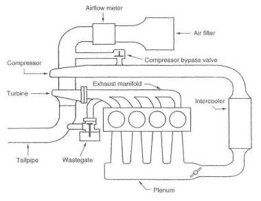
Fig. 5-1. General layout of the intercooled turbocharger system
Removing heat from the intake charge has two huge areas of merit. First, the reduction of temperature makes the intake charge denser. The increase in density is proportional to the change in temperature [measured on the absolute scale). Denser intake charges make more power. Second, but no less important, is the terrific benefit to the combustion process brought about by reduced temperatures in the intake charge. Detonation is reduced by any reduction in intake temperatures. These two areas of merit are the reasons a proper intercooler can increase the power and/or margin of safety of the turbocharged engine. For a discussion of the testing procedures involved in evaluating an intercooler system, please refer to Chapter 14.
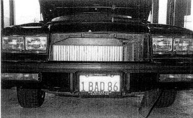
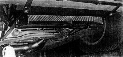
Fig. 5-2. The front mounted intercooler is a typical aftermarket replacement for the Buick GN/GNX series cars.
Design criteria for creating an intercooler are many and varied. These criteria will outline the considerations for building an intercooler that maximizes heat removal and minimizes boost-pressure loss and any lag increases.
Heat transfer area is the sum of ail the plates and shells in the heat exchanger core that are responsible for transmitting heat out of the system. Easy to see that the greater the heat transfer area, the more efficient the intercooler This is not a case, however, where twice the area doubles the efficiency. A10% increase in core will net you about 10% of the amount you did not get out the first time. Therefore, every 10% increase will become less and less important. For example, if an existing intercooler core measures 70% efficient, a 10% core increase should yield about 10% of that missing 30%, or a new efficiency of 73%.
Fig. 5-
Streamlining inside a core is bad by design. The harder it is for air to find its way through a core, the more likely it will give up its heatobviously the major objective. But the bad side is that this poor streamlining can cause large boost-pressure drops. To compensate for bad streamlining, the internal flow area must be made large enough to really slow the air down inside the intercooler, so as to reduce flow drag and keep pressure losses to acceptable levels.
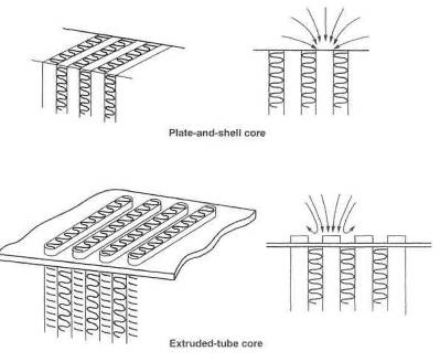
Fig. 5-4. The two moat popular intercooler core styles are plate-and-shell (top) and extruded-tube (bottom}. The plate style generally offers less flow resistance, whereas the extruded-lube style tends to be more efficient. The 'tubes' are typically 1/4' wide by 1 1/2-3' long.
All of the volume internal to the intercooler system must be pressurized before that amount of pressure will exist in the intake manifold. Although this volume is not a large contribution to lag, it is nevertheless a design factor to optimize in the process of creating a good intercooler system. It is a good idea to keep track of the volume and constantly attempt to keep the excess down. A reasonable judgment of the volumes relationship to lag can be made by dividing the internal volume by the flow rate through the system at the rpm at which throttle is applied and multiplying by 2. (The factor of 2 results from the approximate doubling of airflow through the system when going from cruise to boost,) The approximate lag time is given by
![]()
Fig, 5-5. An air duct can provide adequate ambient airflow to a horizontally mounted intercooler.
Example:
Let volume of intake = 500 cu in. and flow rate - 150 cfm at a cruise speed of approximately 2000 rpm.
Then
 sec
sec
It is distinctly possible to upset the basic throttle response if an engine is equipped with an airflow meter positioned too far from the throttle body, Opening the throttle causes a low-pressure pulse to be created that travels upstream toward the airflow meter, The time it takes this pulse to reach the flow-meter and cause it to react is indeed the delay in throttle response. Typically, such a pulse must travel from the throttle body to the intercooler, through the intercooler, back to the turbo, then to the flowmeter, in order for the flowmeter to register a response. It is not until the flowmeter receives this pulse that the air/fuel ratio can change to account for new load conditions in the engine. I should point out that there are exceptions here, based on the style of throttle-position sensor with which the engine is equipped. Nonetheless, it is generally true that the farther the throttle is from the airflow meter, the poorer the throttle response. Thus, this path length should receive some consideration in the design process.
When an engine is equipped with a speed density type of EFI system, wherein no airflow meter is utilized, or a blow-through carbureted turbo system, the length of the intake tract tan extend into the next county with no negative results insofar as throttle response is concerned.
The overall problem in designing an intercooler system, then, lies in maximizing the ability of the system to remove heat from the compressed air while not adversely affecting boost pressure, losing throttle response, or contributing to any delay in boost rise.
The change in density
of the intake charge can be measured relative to the temperature change brought
about by the intercooler. For example, suppose a turbo has a compressor
discharge temperature of
![]()
Therefore, this intercooler will yield a gain of about 19%. This means that 19% more air molecules will be in the combustion chamber than otherwise would have been. All other things remaining equal, one would expect a similar gain in power. This, unfortunately, doesn't come about, because of pressure losses caused by the aerodynamic drag inside the intercooler.
The corresponding power loss due to boost-pressure loss can be estimated by calculating the ratio of absolute pressure with the intercooler to that without the intercooler and subtracting it from 100%.
Example:
If 2 psi out of 10 are lost due to intercooler drag,
![]()
This indicates that flow losses through the intercooler amount to 8%, The idea that the lost boost can easily be recovered by adjusting the wastegate, while attractive, is not quite correct. Certainly, if boost is increased the power will rise, but one consequence of this is that turbine inlet pressure will rise if you attempt to drive the turbo yet harden More turbine inlet pressure creates more reversion, which creates more combustion chamber heat, which reduces charge densitiesand on and on. Thus, one can see that to some extent, recovering lost power by turning up the boost is in part an exercise in chasing one's tail. Tis far superior to design and build the mythical zero-loss intercooler.
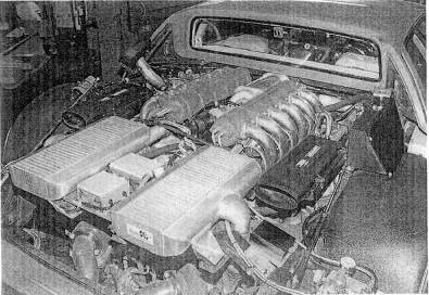
Fig. 5-6. Intercooling taken seriously.
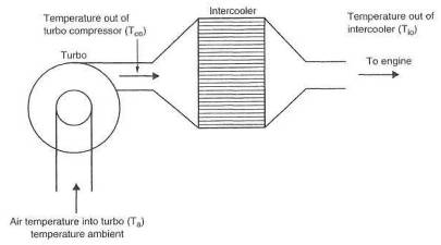
Fig. 5-7. Calculating intercooler efficiency
The idea here is to compare the temperature rise of the intake air caused by the turbo to the amount of heat removed by the intercooler.
Temperature rise
through the compressor is compressor outlet temperature ( ![]() ) minus ambient temperature (
) minus ambient temperature (![]() ).
).
Temperature rise = ![]() -
- ![]()
Heat removed by the
intercooler is the temperature difference between air exiting the compressor (![]() ) and air exiting the intercooler (
) and air exiting the intercooler (![]() ).
).
Temperature removed = ![]() -
- ![]()
Intercooler efficiency
(![]() ) is then the temperature removed divided by the temperature
rise:
) is then the temperature removed divided by the temperature
rise:
![]()
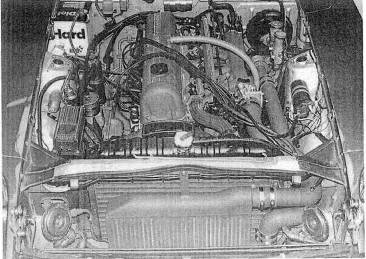
Fig. 5-8. An air/air intercooler mounted in the Nissan 280 ZX.
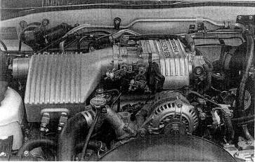
Fig. 5-
Example:
Let ![]() =
= ![]() =
= ![]() =
=
Then
![]()
Currently, there are two types of intercoolers suitable for street use, the air/air unit and the air/water unit. Each has its own areas of merit. The decision about which is most suitable for a particular application is based on the merits of each with regard to the configuration of the vehicle.
The air/air unit will generally have greater simplicity, greater thermal efficiency at high speeds, greater reliability, lower maintenance, and lower cost. The air/water unit will generally have better thermal efficiency at low speeds, better throttle response when a mass-flow meter- equipped EFT system is present, lower boost-pressure loss, and less compressor surge. Space requirements or plumbing complications may dictate that an adequately sized air/air unit cannot be used. Thus the choice is sometimes made without any further consideration.
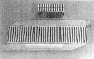
Fig. 5-10. Plate-style intercooler cores offer a good balance of ambient us. charge air flow areas.
A variety of factors must receive equal and adequate attention when configuring the air/air IC. A truly balanced and optimum design is just a cause of working at the details until all facets of the layout are within the specifications outlined in the following paragraphs.
A large part of the pressure loss through the IC system is determined by the internal flow area of the heat exchanger cores.
![]()
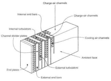
Ftg.5-11. Nomenclature of the intercooler core. The charge air face receives charge air from the turbo. The ambient air face is positioned to receive oncoming cooling air. End ban and plates (typically 1/8' thick}, brazed to the outside surfaces, provide spacing and rigidity. Turbulalors promote exchange of heat from the tubes to the channel divider plates and from there to ambient air through the cooling air channels.
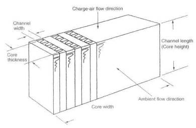
Fig.5-12. Measurement of core flow area.
There is no magic formula for calculating a correct flow area for a given cfm capability, but experience has shown that figure 5-13 consistently yields satisfactory results.
If it were not for the turbulators, which are double-edged swords here, we could make do with much less flow area, but we would experience considerably less heat transfer. The tabulator's job is to see that no laminar flow ever exists inside the core. When this is clone well, each charge air molecule will get its chance to snuggle up to the core walls and exchange its heat energy with the wall. If turbulators are dense heat exchange is better, but flow loss is greater. Conversely, no turbulators at all would yield minimal flow losses, but heat exchange would be lousy. If space is available for a large amount of core material, one can logically choose a core with dense turbulators and trade high turbulator drag for large internal flow areas. The reverse is equally correct: where space is severely limited, a core with low-density turbulators should be selected. Core sizing.
Once internal flow
area has been calculated, actual core size and shape can be determined. With
most cores, approximately 45% of the charge air face is available for entry
into the air tubes. To find the required area of the charge air face, divide
the internal flow area by this 45% figure. Cores are typically available in
thicknesses of 2 and
Example:
Let flow rate = 500 cfm. Fig. 5-13 indicates that a typical intercooler would require an internal flow area of approximately 25 sq in.
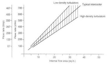
Fig. 5-13. Estimating internal flow area required in the core
Therefore,
![]()
0.45
For a 3-inch-thick core.
56 sq.in
![]()
For a 2-inch-thick core,
![]()
If space is available for the 2-inch-thick core, efficiency will prove a lightly superior, due to the greater width and consequent greater frontal area. Although the thinner core is a better choice, the thicker core is entirely adequate.
The length of the air channels (height) multiplied by the width of the core is the actual frontal area.
In many respects, frontal area reflects the amount of ambient air that goes through the core to cool the intake charge. The greater the mass of ambient air that can get through the core, the greater the cooling capability. The actual rate of flow is the product of the forward speed and the frontal area of the core.
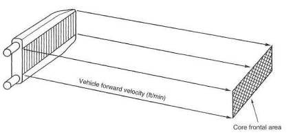
Fig. 5-14. Estimating cooling air available to the intercooler
![]()
Example:
Let s =
![]()
Thus, it is obvious that of two cores with virtually equal internal flow area, the one with the greater frontal area should prove superior.
Streamlining represents the ease with which ambient air can get through the core. Certainly, the easier the air moves through the core, the greater will be the rate of flow and, hence, the greater the cooling effect For example, if the charge air tubes in the core present a rounded edge to incoming ambient air, the rate of flow is likely to be somewhat greater. An engineering factor missing from all core data published is an ambient air drag coefficient.
A duct is in a large sense, a form of streamlining of the core. The ducts present the air molecules with no alternative but to go on through the core. Do not underestimate the ability of a duct to improve the efficiency of the intercooler I would suggest that an improvement of 20% is possible, good duct versus none.
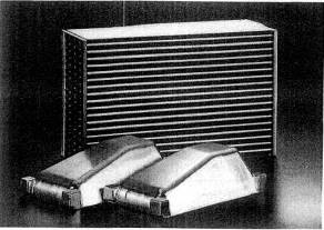
Fig. 5-15. This extruded tube style core is designed for the air/air intercooler application.
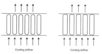
Fig. 5-16. Ambient airflow through the core is proportional to the external drag coefficient of the core. The round-edged extruded-type core will permit more cooling airflow.
When constructing ducts, it is decidedly worth the extra effort to insure that the air molecules have no alternative hut to go through the core. That is, seal all edges, corners, and joints.
It is not necessary for the duct inlet, to be as big as the frontal area of the IC cure. A rule of thumb is that the duct inlet should be at least one-fourth the core area. This rather strange situation is brought about by the fact that less than one-fourth of the air molecules would get through the core with little or no attention to ducting.
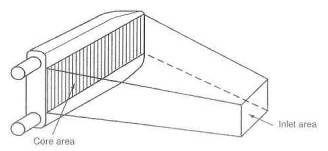
Fig. 5-17. Minimum duct inlet area should not drop below one-quarter of the core area.
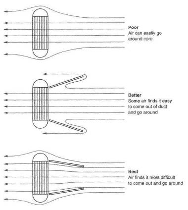
Fig. 5-18. Proper ducting will force more cooling air through the intercooler
Choosing the thickness of the intercooler core is a bit of a juggling act similar to the turbulators. The juggling act is brought about by the fact that the second half of any core does only one-fourth the work.
Adding thickness to the core will indeed improve efficiency, but the gains become less and less. Another negative effect is brought into play by increasing the thickness: the increasing difficulty of getting the ambient air to pass through the core. Essentially, then, the drag coefficient of the core goes up as thickness increases. A clever way to package cores where frontal area is scarce and depth abundant is the staggered-core IC discussed later.
When adequate apace exists For a large IC, the decision must be made about the direction in which to orient the core. Unless overwhelming reasons dictate otherwise, the core should always he constructed to provide the greatest possible internal flow area. The direction of flow is unimportant. For example, the ICs in figure 5-15 take up the same space, but the vertical-flow unit has more internal area and, hence, considerably less restriction.
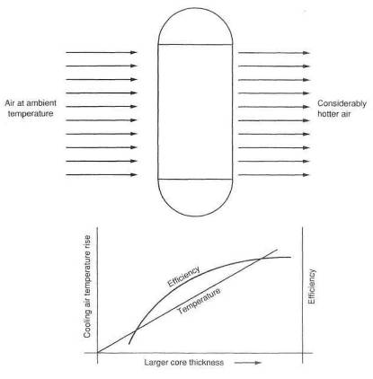
Fig. 5-19. Increasing core thickness does not proportionally increase heat transfer capability. Each increment of core thickness will receive hotter cooling air.
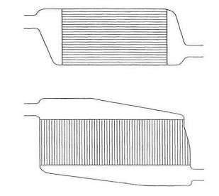
Fig. 5-20. The top and bottom cores have the same frontal area, heat transfer area, and efficiency, bid the bottom core has much greater internal flow area, due to the larger number of tubes and, therefore, lower pressure loss.
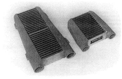
Fig. 5-21. This is the proper way to make a bigger intercooler. Always increase the core area by adding a greater number of internal passageways. Do not just make the same number of passages longer
Several details in the design of the end tanks fitted to the IC cores can both improve thermal efficiency and decrease flow losses. It is certainly not a good idea to suggest that all those molecules of air can easily and conveniently find their own way into and out of the intercooler. Think in terms of herding sheep. Give them direction and guidance and make the journey easy for them.
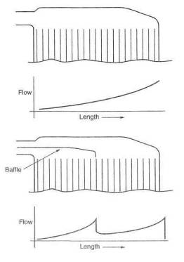
Fig. 5-22. Proper internal baffling can create more uniform airflow distribution through the core and, thus, greater heat rejection. Add the baffle to force half the charge to go through the first half of the core and the remainder through the second half
It is fundamental that thermal efficiency will improve if we can get equal distribution of airflow through the core tubes. A serious attempt at accomplish ing this can be made by suitable battles built into the in-cap.
The position of the inlet to the in-cap should receive attention in several areas. Keep uppermost in mind the requirements of air distribution and ease of flow
After the distribution job is done by the in-cap, it is the out-cap's lot to gather up all the molecules and point them toward the engine. This must be done with equal attention to streamlining, to keep flow losses to a minimum. Point the sheep in the direction of the exit, give thorn room, and don't make them do anything sudden. Do not offer them any abrupt changes in direction.
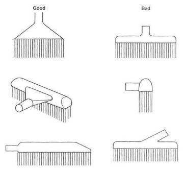
Fig. 5-23. Good and bad end-cap designs
There is probably a
magic number that airflow velocity in a tube should not exceed, for reasons of
rapidly increasing drag and consequent flow losses. 1 suspect this number is
around Mach .4, or about
Example:
Let power = 400 bhp,
for which maximum airflow is approximately 600 cfm, and air tube diameter =

The speed of sound is
approximately
![]()
Thus, the 2.5-inch-diameter tube will be adequate to flow 600 cfm without unreasonable drag.
Resist the temptation to use larger diameter tubes than necessary, as little drag is created in smooth tubes with gentle bends. Larger tubes will only add to the volume of the IC system, and that is not a good thing to do.
Any bend in a tube or sudden change of cross section must be viewed as a potential flow loss or source of increased drag. It would be reasonable to estimate that every time the airflow must turn 90, a loss of 1% of the flow will occur. Three 30 bends will add up to a 90. Always use the largest possible radius for any change of direction.
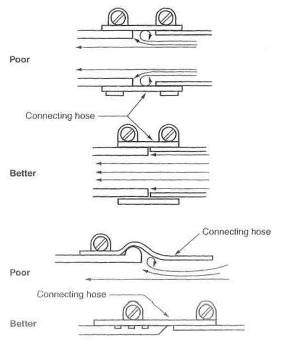
Fig. 5-24. Minor flow interruptions can exist at tube intersections.
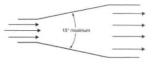
Fig. 5-
Certainly a short-radius 90 bend will lose more flow than a large 90. The change from one size tube to another is frequently necessary for purposes of getting into a throttle body, out of the turbo, and into and out of the intercooler. These changes of section upset smooth flow and create losses.
Gradual changes of section can best be created by conical segments, A reasonable rule of thumb for the angle of the cone would be one diameter change in four diameter lengths.
All hoses and connections spell trouble. At the outset of designing a turbo system, consider all hoses and connections the weak links of the intake system, Failure of a hose connection will certainly mean a lass of boost pressure. However, where a mass-flow-meter-controlled EFI is used, the engine will no longer run. When a hose fails, the engine can get air around the mass flowmeter, and thus the meter loses its ability to generate the proper signal. Without the proper signal, the engine will run poorly or not at all. The problem with hose joints stems from the fact that each joint has a load trying to push it apart equal to the cross-sectional area of the tube times the boost pressure.
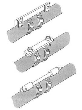
Fig. 5-26. Tie bars on intercooler tubes relieve tension on the connecting how.
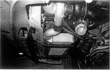
Fig. 5-27. Adequate airflow to an air/air intercooler is a must for good efficiency. This intercooler would benefit from a scoop rather than ike air dam.
If a system runs 20
psi boost through a 2-inch ID hose joint, it will have
The poor hose is trying to do all this load-carrying in a hot, hydrocarbon-fuel-rich environment. It is necessary, then, to seek hose material impervious to hydrocarbon fuels and exhibiting little degradation at the temperatures involved. Such hoses are generally made of silicons-based material.
The place to put an intercooler so often boils down to finding available space for a big enough unit. That doesn't take much science. A few rules, however; should receive some forethought. Try hard not to put an air/air intercooler in the same compartment as the engine. Placing it behind the cooling system radiator is also out.
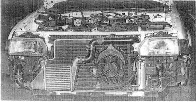
Fig. 5-28. Devious plumbing is sometimes required to fit an air/air intercooler into the system. Keep tubes a little larger and the number of bends to a minimum.
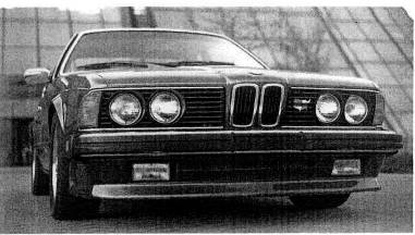
Fig. 5-
Consider that air
having passed through the cooling system radiator is generally
Indeed, the turbo, in low boost ranges, may not heat the intake charge up to the temperature level of the underhood air that is being asked to cool the intake charge. When this happens, the intercooler becomes an 'interheater' not a good turbo part. When the boast rises to the point that the temperature of the charge exceeds the underhood temperature, the IC will begin doing some work but will forever suffer from a severe efficiency loss. Not what we want. Underhood radiation of heat to the IC can also be a problem. Insulation and ducting can help these problems, but, fundamentally, the engine compartment is no place for an intercooler.
** RULE: Always be on the lookout for the villain called the 'interheater'
In a situation where frontal area space for an IC is limited but abundant depth exists, the staggered-core IC should be considered. Basically, the staggered-core IC is just a thick core unit with the back half moved aft a bit. Some fresh air is ducted to it, while the used air from the front core is sent around the second core. A compact, high-flow IC can be built with the staggered-core concept. Efficiency can be high, because the rear half of the IC is made to do its share of the workload.
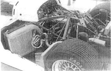
Fig. 5-30. The all-conquering
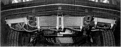
Fig. 5-31. Front watercoolers for a water-based intercooler system
The water-based intercooler system becomes an attractive alternative to the air/air unit when space or plumbing restrictions preclude use of the latter. The logic behind most of the design criteria for the air/air IC applies as well to the water-based IC. Obviously, there are different considerations for handling the water. Although complex, the water-based IC enjoys the one terrific advantage of the far greater (fourteenfold) heat transfer coefficient between water and aluminum than between air and aluminum.
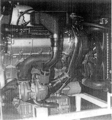
Fig. 5-32. This installation of the water-baaed intercooler onto the Maserati bi-turbo clearly illustrates its compactness.
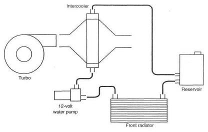
Fig. 5-33. General layout of a wafer-based intercooler
This huge difference is of huge value only if all the heat transfer barriers can be optimized such that the 14-to-1 rate can be of benefit. This is the path to the intercooler system that exceeds 100% for thermal efficiency. Presently this is not practical for any situation except a drag car, Bonneville runner, or marine application. The solution to the problem is in need of the services of a genius inventor type. Without any ingenious solutions, the water-based IC reverts to nothing more than an air/air unit in which the intake charge heat is carried to the front of the vehicle for exchange into the atmosphere by water rather than by the intake charge itself.
The focus of the problems on handling the water is largely centered around rate of water flow, amount of water in the system, and the subsequent removal of heat from the water
It is easy to get a large internal flow area inside the water IC, since the most usable cores for this purpose are often air units with the flow reversed.
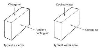
Fig. 5-34. When using a typical air/air core as a water heat exchanger, reverse the direction of charge air flow to obtain greater flow area.
Although aluminum is by far the most convenient material to use in any IC application, copper core elements, should the situation allow them, can yield a greater heat transfer rate. The large flow areas usually associated with the water IC readily suggest that core thickness should be expanded as far as space permits.
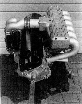
Fig. 5-
Water will likely find
equal access to all the core tubes, but attention should be given to trapped
air in the top regions of the core. A simple air bleed can prevent air
pockets. A better answer is to put the water in at the low point and take it
out at the
Small air leaks in an air/air unit are unimportant, but any water leak in the main heat exchanger core can be a disaster. Thus it is imperative that the unit be pressure checked For leakage prior to use. Ten psi with the core underwater is adequate. Don't be surprised to see air bubbles coming right through cast aluminum .
Easily the most usable
pumps are 12-volt marine bilge pumps. These can be ganged in series or
parallel, depending on pressure and flow capability of the pumps. The
fundamental should not he overlooked that the more water circulated, the
greater the IC efficiency. Consider a water flow rate of
Wiring the pumps to a switched 12-volt source will permit an audible inspection of their function every time the ignition is turned on. The pumps should be mounted as the low points of the IC system, so that they will always be primed and thus preclude the chance of their running dry.
Water is by far the best cooling medium. Glycol and other antifreeze materials degrade the ability of water to transport heat and should be used only in quantities required to prevent freezing and corrosion.
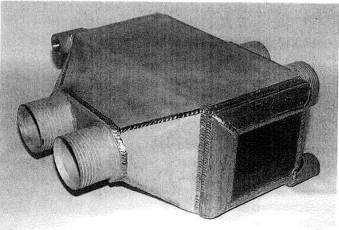
Fig. 5-36. An offshore racing boat is the ideal situation for a water-based intercooler. The seawater coolant with a temperature below ambient air offers the megahorsepower racing boats an intercooler with the potential to exceed 100% efficiency. This unit was designed for a 1500 bhp twin-turbo, big-block Chevy.
Essentially, put the same ratio of water and antifreeze into the IC that is used in the engine cooling system. Use of a modern coolant can offer the further benefit of protection from aluminum corrosion. Distilled or demineralized water will keep the system clean.
The size of the
reservoir is of primes importance to the efficiency of the water-based IC.
Consider that most applications of boost will last only a few secondssay, 15
as a high average. Then it is reasonable to be sure in this interval that any
given piece of water will not see the IC unit twice. A pump capability of
The front cooler is
the least important part of the IC system, as it is doing most of its work when
the vehicle is not operating under boost. At the start of a boost run, the
entire system will be at approximately ambient temperature. As boost rises,
heating the water in the main core, this heated water must get to the front
core before it has any temperature difference with which to drive the heat out.
This time delay can be as long as 7 or 8 seconds, depending on the size of the
reservoir. That amount of time is typical of a boost application. It is clear,
then, that the front cooler will do most of its work after the boost run. Since
the temperature difference between the water and the front core is small
compared to the temperature difference between the boost charge and the water,
the time required to cool the water down is much greater than the time required
to heat it up. This is another reason for running the water pumps ail the
time. The front core does not need to be as big as it may seem at first glance,
because the relative cfm rates through the two cores will usually be heavily
biased toward the front cooler. For example, a forward velocity of just
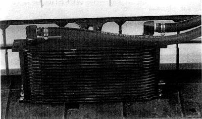
Fig. 5-37. The water-based intercooler must have a front-mounted heat exchanger. The compactness and efficiency of oil coolers makes them ideal for this application.
Spraying water onto an IC core, presumably an air/air unit, is a method of improving thermal efficiency of the IC. Preliminary testing of such a mechanism has been shown to offer an easy improvement of 5 to 10%. The design and use of any cooling system based on a consumable fluid is best considered for special events only.
The water injector is not a very interesting device. It has little place in a properly conceived turbo system. Two circumstances are viable for a water injector: a 1970 home-built Vega turbo with a draw-through carb, or a Roots supercharger sitting between a huge engine and two huger (really big) carburetors. To stake the margin of safety of a turbocharged engine on an inherently unreliable device is an idea whose time has long since passed. RIP.
Special-purpose events like drag racing or top-speed trials lend a note of keen interest to the one-shot, superefficient intercooler. While not yet practical for everyday use, intercoolers operating well in excess of 100% efficiency can easily be created and used to great advantage for short durations. The principle behind the 100+% efficient intercooler is that of providing a cooling medium for the heat exchanger core that is either below ambient temperature or that can absorb huge amounts of heat by the evaporation process when in contact with the core. Examples of each would be an ice-water-bathed core or one sprayed with liquid nitrogen. Keep in mind that whatever the cooling medium, it must be kept in motion at all times, to avoid boundary layer formation. A stationary boundary layer will get warm and severely restrict the flow of heat from the core. Don't get carried away with gleeful thoughts of how great a 100+% intercooler will be and overlook that equally important design aspect of pressure loss through the core.
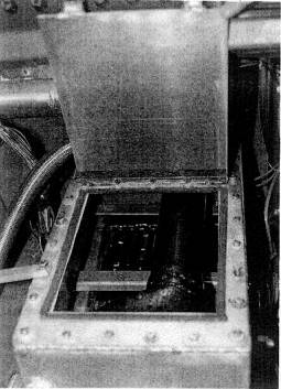
Fig. 5-38. An ice-chest heal exchanger for a one-shot intercooler for drag racing. Ice is packed around the water tubes, and the container is then filled with water.
What is an intercooler, and why is it of merit?
The intercooler is a heat exchanger (radiator) placed on the turbo compressor outlet. Its purpose is to reduce the temperature of the compressed air coming out of the turbo, increasing air density and allowing; higher boost pressures.
This change in temperature has two distinct advantages; it increases power and it staves off detonation to considerably higher boost pressures. Cooling a gas makes it denseri.e., more molecules per cubic inch. The density increase will generally be around 10 to 15%, depending on boost level and cooler efficiency. Power increases proportional to density. This is certainly a useful increase in power but nowhere near all that is safely available. The increased margin of safely on detonation is so great, due to the temperature reduction, that a portion of that margin of increase can be used to raise the operating boost level In my experience, detonation will be suppressed a further 4 to 5 psi boost with a proper intercooler- (provided a correct air/fuel ratio is present). Operating boost pressures can and should then be raised 3 or 4 psi. The improvement in performance as a result of this additional 3-4 psi intercooled is approximately the same as the performance provided by the first 5-6 psi of boost.
However, there can be pitfalls, First, it is currently in vogue to offer an intercooler as a substitute for a correct air/fuel ratio. Can't do it. A correct air/fuel ratio is imperative. Must have. If your choice is one or the other, you must choose the correct air/fuel ratio. Both are the best situation, by far.
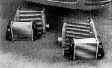
Fig. 5-39. Increased intercooling for factoty turbo cars should be accompanied by modest boost increase.
Second, too great a pressure loss pumping through an intercooler can raise exhaust manifold pressure by such a large amount as to demolish virtually all the power increase offered by the intercooler. A zero-resistance intercooler is ideal Get as close as you can. Know what you buy. Ask what the pressure drop is at 1.5 times the cfm rating of your engine, It should be less than 2 psi. Few will be, OEM included.
What configurations- do intercoolers come in?
There are two basic styles of intercoolers: air-to-air and air-to-water. Each has distinct merit, yet each has some problems, Air-to-air is the simplest. It has no moving parts and is as reliable as a brick.
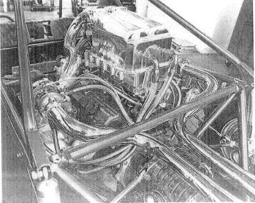
Fig. 5-40. An elaborate yet effective water-based intercooler built by Jim McFarland, Mechtech Motorsports, for his unique Nissan V-6 twin- turbo-powered four-seater sand car
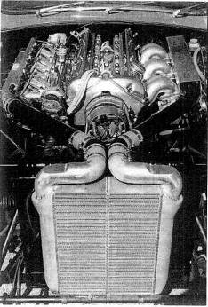
Fig. 5-41. Even an old XKE Jaguar can sport an intercooler, but don't, block all the cooling system airflow.
Heat-transfer capability is adequate, but pressure losses can be high, particularly with the small cores generally used. A given pressure loss through the intercooler will show up as an increase of twice that in the exhaust manifold pressureone of the devils of turbocharging. All in all, a good unit if sized for adequate heat rejection and minimum pressure loss.
The air-to-water unit suffers a bit from complexity, but it does perform. It is composed of two radiators, one between the turbo and the engine and a smaller one in front of the standard cooling-system radiator. The water is circulated by an electric pump.
Decisions on which unit to use must be based on the engine, available space, fuel injection flow sensors, and a variety of other factors. An example of each: the obvious choice for 6-cylinder BMWs is a water-based unit, since no space exists for adequately sized air/air cores. Further complicating the air/air unit in the BMW 6 is a complete lack of high-velocity air in the only space where even a small core will fit. On the other hand, the Ford Mustang GT offers an ideal situation for the air/air unit in all respects. The space exists for a truly huge air/air unit (three full cores), and it sits in a great airflow spot.
What is water injection, and when is it needed?
Water injection is the
spraying of a fine stream of ![]() into the intake system. Heat absorbed upon vaporization of
the water has a strong cooling effect on the hot compressed air exiting the
turbo. The reduction in intake air temperature reduces the tendency to knock.
into the intake system. Heat absorbed upon vaporization of
the water has a strong cooling effect on the hot compressed air exiting the
turbo. The reduction in intake air temperature reduces the tendency to knock.
Don't be too hasty to create a margin of safety on detonation based on an unreliable device. Water injection is best used when boost levels over 6 psi are desired but no intercooler is present. Do not allow a situation to exist where the water injector is used as an excuse for improper air/fuel ratios. All things considered, you would be far ahead never to have heard of a water injector.
|
Politica de confidentialitate | Termeni si conditii de utilizare |

Vizualizari: 3299
Importanta: ![]()
Termeni si conditii de utilizare | Contact
© SCRIGROUP 2025 . All rights reserved