| CATEGORII DOCUMENTE |
| Bulgara | Ceha slovaca | Croata | Engleza | Estona | Finlandeza | Franceza |
| Germana | Italiana | Letona | Lituaniana | Maghiara | Olandeza | Poloneza |
| Sarba | Slovena | Spaniola | Suedeza | Turca | Ucraineana |
The modern turbocharged automobile has brought new meaning to the term 'free-flow exhaust system,' with its connotation of low back pressure. The modern exhaust system also invariably has a catalytic converter, with its implication of high back pressure. At first glance, these two items are somewhat at odds with each other. At last glance, the situation is a bit better than generally believed. If the turbo could step up and dictate terms for design of exhaust systems, it would categorically state: None! If the feds could step up and dictate the design of exhaust systems (which they can, have, and will continue to do), they would state that the best tailpipe is one that nothing comes out of. Somewhere between these two dissimilar requirements lies a real good exhaust system for street use that will keep both parties happy. Well, relatively happy.
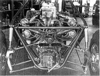
Fig. 11-1. The best exhaust for a turbo is the least exhaust.
For our purposes, we shall call the exhaust system everything after the turbo. Virtually all turbos require special tailpipes. Stock, non-turbo tailpipes don't cut it. Seldom do aftermarket tailpipes prove satisfactory either. An exhaust system is an accumulation of optimized, carefully thought out features. The objective that must be met in correlating these design features is the creation of a clean-running, acceptable-noise-level, lowest-possible-back-pressure tailpipe.
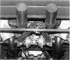
Fig. 11-2. Turbos do not like back pressure; the lower the better. Note the separate exhaust pipes for the wastegates.
Turbo-to-Tailpipe joint. This part of the exhaust system is subject to
temperatures ranging up to
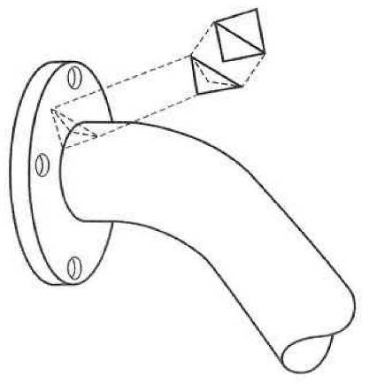
Fig. 11-3. Strengthening ribs between each fastener will greatly increase the durability of a flange-to-pipe joint.
As flanges do not stay flat during welding, the mating surface to the turbine must be surfaced prior to installation. Welding is generally harmful to the base metal, A weakened condition thus exists at the flange/tube weld. An easy way around this weak point is to weld the tube inside the flange and only intermittently on the outside, making the weak segments discontinuous.
Basic tube size. it is easy to get overeager on fitting large-diameter pipes into an exhaust system. 'The larger the better' is not the case. As indicated in Chapter 5, there is an exhaust gas velocity that ought not to be exceeded. I am going to suggest that for exhaust calculations, this velocity is approximately 250 ft/sec. The considerable expansion of exhaust gas due to the temperature increase also requires a significant increase in the desired volume of the tailpipe. The tubes for the hot gas on the exhaust side should therefore be larger than the tubes for the cooler intake side. Base the calculation on the same conditions as for intake tubes, but use a maximum velocity of 250 ft/sec rather than 450 ft/sec. To size a tailpipe, you can adhere to this exhaust gas velocity or to the simple guideline of selecting a tube diameter approximately 10% larger than the turbine outlet diameter. Figure 11-4, exhaust tube size versus bhp, offers a good guide to choosing an adequate tailpipe size.
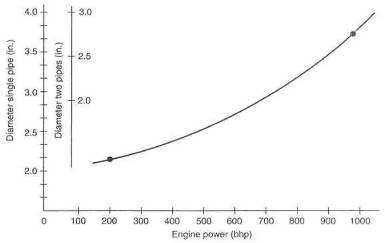
Fig. 11-4. Approximate exhaust pipe flow area for specific power output
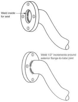
Fig. 11-5. Turbine outlet flange connections should not be welded a full 360' on the external joint.
Converter position. The position of the catalytic converter is locked in by law. The converter must stay in the original position. Do yourself a favor and leave it alone. Modern matrix-style converters are not very restrictive, Most units will contribute less than 2 psi to the total back pressure in the tailpipe. That is acceptable.
When adding a catalytic converter to a system not previously so equipped, place the converter as close to the turbo as possible, to help the converter reach operating temperature quickly.
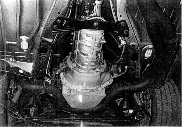
Fig. 11-
Oxygen sensor position. The oxygen sensor ideally wants to be as close to the combustion chambers as temperature permits. In most circumstances where a turbo is involved, the oxygen sensor should be immediately aft of the turbo.
Expansion joints. The wide temperature fluctuations experienced by the tailpipe of a turbo engine cause somewhat greater thermal expansion than would otherwise be the case. Permitting the tailpipe to expand and contract without restraint thus becomes vital, to avoid cracking caused by thermal-expansion-induced binding.
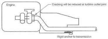
Fig. 11-7. Thermal expansion of the exhaust system must be allowed to avoid cracking.
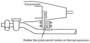
Fig. 11-
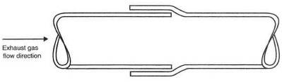
Fig. 11-9. The swaged tailpipe joint is the simplest and most versatile of all joints.
A degree of flex can be built into a tailpipe, with swages used as connectors for the pipe segments. Swages permit easy angular adjustment as well. The pipe clamp can also readily serve as a hanger anchor
Hangers. As simple as the idea may be of hanging a tailpipe under a car, you need only look under a Ferrari to get a good feel for the fact that this subject can be taken very seriously. Several problems crop up up properly locating a tailpipe. Vibration, heat, engine rocking motions, thermal expansion, and hanger design are all problems that need to be addressed before one has a durable, unobnoxious tailpipe.
Vibration can usually be damped by frequent hangers and soft spots. Soft spots are flex joints that will not transmit vibration. A swaged joint is an example of a soft spot.
Heat is only a problem if a vulnerable component is within range. In general, it is far better to insulate the item that can get damaged rather than the tailpipe itself. Heat can damage such things as undercoating, fiber materials, and painted surfaces. A bit of time spent looking for such vulnerable things and providing a few shields will prove valuable in the long run. A simple sheet-metal shield will provide a temperature drop of several hundred degrees.
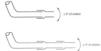
Fig. 11-10. Swages, either singly or in multiples, can be used as flex joints.
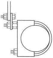
Fig. 11-11. Simple hanger with clamp
Muffler styles, sizes, and number. Generally speaking, the muffler will be the largest single restriction in the exhaust system. Unfortunately, the requirements of low hack pressure and silencing are usually at odds with each other. Reasonable compromise can be reached most often with several large mufflers. The need to keep large flow areas through all sections of the exhaust system can frequently he met by installing mufflers in parallel. Inspect the flow area available in each case and be certain the sum of the cross-sectional areas exceeds the basic tube area. It will pay dividends to make the muffler flow areas about 25% greater than the basic tube, as the drag coefficient inside the muffler is usually pretty shabby.
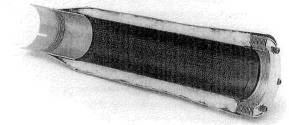
Fig. 11-12. The clever yet effective low-restriction muffler design from Super-Trap.
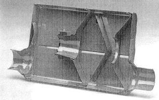
Fig. 33-13. The Flow-master muffler offers low exhaust gas restriction with adequate noise suppression.
The choice of muffler styles is limited to straight-through glass-pack types or the relatively popular 'turbo' mufflers. Generally, straight-through unite offer better flow capability, while baffle-style turbo mufflers provide superior silencing, Glass- or steel-pack units have the reputation of burning the silencing material out at an early age. Oddly enough, the turbo dramatically extends the life expectancy of these mufflers, as it takes out a great deal of heat that would otherwise do damage.
Two types of cores are popular in the glass-pack units: drilled and louvered. Drilled cores have a much cleaner, thus less restrictive, flow path. If drilled-core units prove scarce, louvered-core mufflers work better when flowed backward.
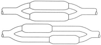
Fig. 11-14. Top: Parallel glass-pack mufflers flow well and offer low restriction. Bottom: This muffler layout may offer an advantage in tight spaces.
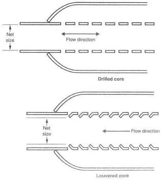
Fig. 11-15. Glass-pack mufflers are made in two different styles, drilled-core and louvered-core. Drilled-core are superior.
Fear of excessive noise with straight-through mufflers is usually valid. This is not the case with a turbo engine, as the turbo alone can be considered approximately one-third of a muffler.
Wastegate integration. The wastegate, discussed more extensively in Chapter 12, presents no special requirements with respect to silencing but does create an opportunity that can benefit performance. In any catalytic-converter-equipped car, the wastegate discharge must be put back into the tailpipe before the converter, because all the exhaust gas must pass through the converter. Where no converter is required, the opportunity exists to make a completely separate tailpipe solely for the wastegate. A simple muffler may prove necessary to keep noise within limits when the system is at maximum boost. The value in creating a separate tailpipe here is that it effectively increases the exhaust system's total flow area. In general, a wastegate will be more positive in response and somewhat more effective in controlling boost pressure when accompanied by its own tailpipe.
The wastegate vent tube or tailpipe will suffer unusually large fluctuations in operating temperature. This situation exists because the wastegate is closed most of the time, and the vent tube will thus be cold, since no exhaust flow is present. As soon as the wastegate opens, the entire vent tube experiences a rapid rise in temperature.
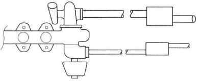
Fig. 11-
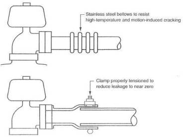
Fig. 11-17. The wastegate vent tube suffers the most from thermal expansion; length changes must be accommodated. Note direction of swage for best seal when not operating under boost, due to normal back pressure in the tailpipe.
This fluctuation will
occur every time the wastegate opens. This requires the vent tube design to be
such that it can expand and contract without putting itself in a crack-inducing
bind. Expansion joints can take the shape of swaged or bellowed connections.
Bellows, to prove long-term durable, must be stainless steel and of sturdy
construction. The material should be a minimum of
Materials and finishes. Mild steel is an entirely adequate material for exhaust system construction. Stainless steel, while distinctly superior, presents the problem of obtaining all the system components from this material. Stainless tubes welded to mild steel mufflers accomplishes little for long-term durability.
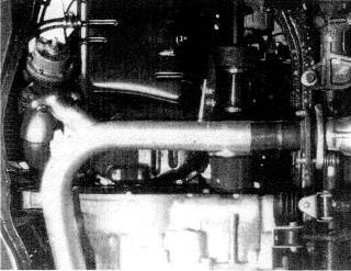
Fig. 11-18. This wastegate on a Honda CRX is mounted remotely from the exhaust manifold for packaging reasons.
Fasteners and gaskets. Bolted-together joints are surely the most troublesome parts of any exhaust system. If properly configured, the fasteners and gaskets that hold the joints together can go a long way toward insuring that these joints remain in service without trouble. Creating the correct setup is largely a matter of several do's and don'ts, listed in Chapter 10.
Flanges. A flange has the twofold responsibility of keeping the gasket securely clamped at all times and insuring that the tailpipe tube receives adequate support. These requirements are easily met by using flanges 3/8 inch thick or greater. A small flange, such as for a wastegate, can survive as thin as 5/16 inch. In general, the thicker the flange, the longer it and its gasket will stay there.
Since the only visible segment of the entire exhaust system is the last few inches, it is tempting to let style do a number on efficiency, Style is almost always nice, but not when it costs power. Make sure the exhaust flow area is maintained through the tips. Thoughts of tip designs that 'extract' exhaust gases might be alluring, but wait until they show up on Formula 1 race cars before getting too enthused about their merit. Most fancy tip offerings will prove less than satisfactory.
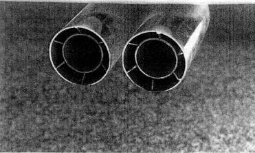
Fig. 11-19. Nice cosmetic exhaust detailing from Borla. The outer tube is the basic pipe size.
A front-wheel driver is most often a transverse engine layout. This presents a new problem to the designer, in that the tailpipe is required to flex up and down when the engine moves relative to its mounts when transmitting torque. It is not feasible to bend a tailpipe and expect it to survive more than one fast lap around the block. The flex joint takes on a whole new meaning with the front-drive transverse-engine vehicle. Don't put yourself into the position of building pipe after pipe with the strength to stay in one piece and trying to get one to live. The problem is to design in enough flexibility of joints so that the engine can move virtually anywhere and not overstress the tailpipe. Anticipate 10 of flexibility and provide for it.
Do the joints interfacing the turbo have any reliability problems?
Almost always. Stock systems are designed for flow rates produced by stock engines. To try to pump 50% more flow (approximately 7 psi boost) through an exhaust will raise tailpipe pressure to an unacceptably high level.
|
Politica de confidentialitate | Termeni si conditii de utilizare |

Vizualizari: 2742
Importanta: ![]()
Termeni si conditii de utilizare | Contact
© SCRIGROUP 2025 . All rights reserved