| CATEGORII DOCUMENTE |
| Bulgara | Ceha slovaca | Croata | Engleza | Estona | Finlandeza | Franceza |
| Germana | Italiana | Letona | Lituaniana | Maghiara | Olandeza | Poloneza |
| Sarba | Slovena | Spaniola | Suedeza | Turca | Ucraineana |
Guidance of airflow into the cylinder head is the job of the intake manifold. Control of the amount of flow is the function of the throttle.
A fuel-injection-equipped engine will usually flow an air/fuel mixture over a short portion of the intake manifold passages, whereas a carbureted engine will flow the air/fuel mixture through the entire length of the manifold. These two different characteristics create vastly different design requirements.
The basic layout of the fuel injection manifold will be determined by its application. A racing; application will generally tend toward a design with one throttle plate per cylinder. Typically, a street manifold will employ just one throttle plate or one multiple-plate progressive throttle body, attached to a plenum that will feed all cylinders. The one-plate-per-cylinder style will exhibit lower flow loss and is thus more suitable for maximum power. With just one plate total (or one progressive throttle body), a considerably crisper intake manifold vacuum signal is generated. This greatly increases the accuracy with which low-speed fuel and ignition can be calibrated and is thus better suited to a street-driven automobile.
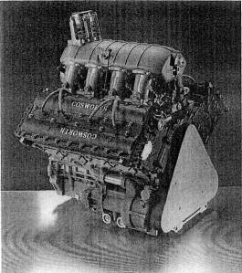
Fig. 6-1. The Cosworth V-8 is one of the greatest racing engines in history. In its turbocharged Indy car form, it shows the way to high-performance intake manifolding, throttling, and plenum sizes and shapes. Note the throttle position at the lower front of the plenum. The throttle inlet sweeps upward into the center of the plenum.
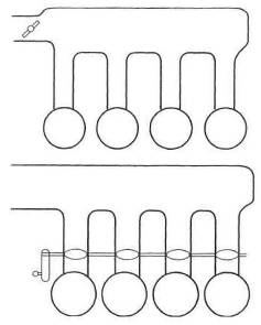
Fig. 6-2. Top: Log-style intake manifold with a single throttle inlet. Bottom: Plenum manifold with multiple throttle plates
Synchronizing the flow, cylinder to cylinder, through multiple throttle plates is another matter altogether.
The two vastly different applications have many features in common. Both require an ideal shape for air inlets into the runners to the combustion chambers. Both require considerable thought as to the rate of taper of the port runners. In all applications, it is desirable to accelerate air toward the combustion chamber. This is done by gradually reducing the section area of the runner as it nears the chamber. Accelerating the air to a reasonably high velocity is beneficial, because it promotes chamber turbulence, yielding better combustion. Better chamber filling, which creates more power, will also occur.
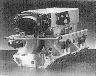
Fig. 6-3. The big-block Chevy Super Ram manifold/plenum/ throttle assembly. A compact design with short runners and good inlet shapes that work well at high flow rates.
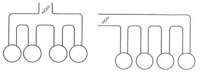
Fig. 6-4. The symmetrical intake manifold (top) has a higher probability of equal flow to each cylinder than the more compact non-symmetrical design.
The length of the runner has a strong effect on the amount of air that actually gets into the chamber during the intake valve cycle when the engine is not under boost. Due to its complexity, this phenomenon is best studied separately from turbo design. Here, it is sufficient to say that higher-speed engines will tend toward shorter intake runners. Low-speed and mid-range torque generally shows gains from longer runners.
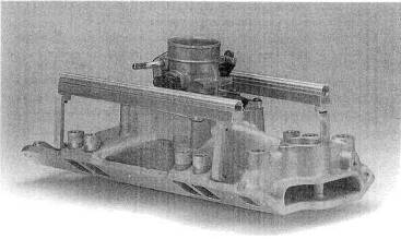
Fig. 6-
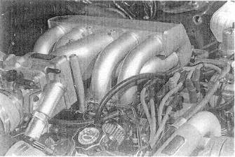
Fig. 6-6. Individual intake runners from a plenum are useful design features. A good example of a symmetrical design.
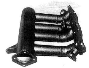
Fig. 6-
Turbo applications will generally find best results with long runners, which provide a broad, flat torque curve at low speeds, while the turbo keeps the top end strong. In the fuel injection application where only air is moving inside the runners, the runner design becomes free to go up, down, or sideways.
Symmetry of design is a desirable characteristic, either rate or street, as it facilitates equal distribution of airflow to each cylinder.
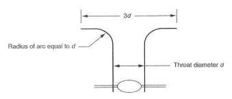
Fig. 6-8. Ungainly, perhaps, this is the shape of an ideal air inlet.
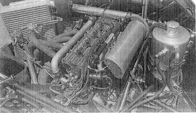
Fig. 6-9. An intake plenum should be several times larger than a cylinder's displacement. This Ford GTP car satisfies that requirement well
Virtually all fuel injection manifolds will have a plenum. The plenum volume should be a function of engine displacementin general, 50 -70%. One of the critical design points in the manifold is the plenum-to-runner intersection. This is the point at which a bell-mouth-shaped inlet to the runner must be carefully made.
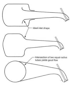
Fig. 6-10. The shape of the intersection between plenum and intake runner must approach the ideal air inlet shape.
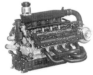
Fig. 6-11. This Porsche Indy engine dearly illustrates plenum size requirements.
Only two basic rules apply to the location of an injector. First, it must be aimed as straight down the center of a port as possible. Second, it should discharge at a point where air velocity is at or near its highest.
Occasionally a system will have such a large airflow or rev range that a single injector cannot provide enough fuel. In such circumstances, at least a secondary fuel injector will be required, and sometimes even a third. Alignment of the secondary injector is not as critical as the primary, because the secondary is generally not used until the system has achieved a relatively high rate of airflow. In street applications, it is still desirable to point the secondary injector downstream. Race applications, however, have occasionally aimed the secondary back upstream, Although data are scarce, this may offer slightly better atomization and is worthy of consideration.
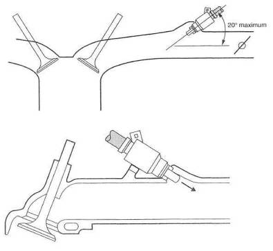
Fig. 6-
Fig. 6-13. An upstream injector
The throttle body is usually one of the serious airflow restrictions in the turbocharger system. Simply making the throttle bigger will alleviate the problem, but low-speed driveability can become an on/off, jumpy proposition, A big throttle plate open a small amount can let in a lot of air, and smooth low-speed throttle response will suffer. A maximum air velocity of approximately 300 ft/sec will keep flow losses acceptable. Air velocity can be calculated by
![]()
Example:
Let cfm = 500 and
throttle throat ID =
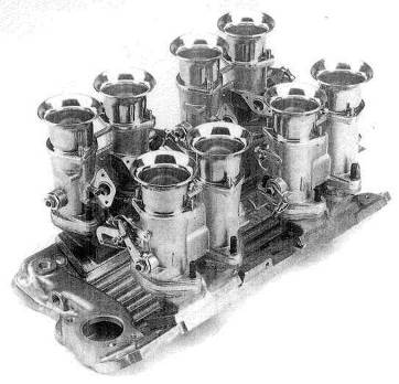
Fig. 6-14. EFI throttle bodies on a Chevy small-block manifold. With one throttle plate per cylinder, this is one of the lowest-restriction throttling layouts.
Then

If 300 ft/sec is exceeded and the single throttle plate is not accompanied by a progressive linkage, it would be time to consider a two-plate progressive throttle body.
For race applications where one throttle plate per runner is employed, it is quite adequate to sum the throttle plate areas and calculate accordingly, or simply to use one cylinder and one throttle. The 300 ft/sec figure should still offer a suitable guideline.
The beautiful race hardware utilizing slide-valve throttles should generally be avoided, because the area times pressure usually yields forces of large magnitude. Special bearings and linkages can make the slide valve workable. In general, life is vastly simplified with the standard old twist-shaft throttle plate.
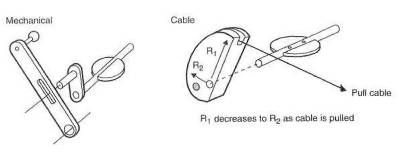
Fig. 6-15. The progressive throttle linkage is a simple concept and effective at producing smooth operation at low engine speeds.
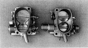
Fig. 6-16. Neuspeed's large VW throttle body is a progressive unit with obvious value for custom turbo applications.
The attraction of a two- (or multiple-) plate progressive throttle body can be strong. The application needs careful analysis, since the progressive is not always of the benefit it may seem. The best place to use the progressive is with large engines that accelerate well at low speeds with little throttle opening. Generally, avoid the progressive on small engines that require a lot of throttle just to make them move.
Although seriously on the decline, and with good reason, a few more carbureted turbo systems will certainly be built. Such a huge number of intake manifolds are in production today that selecting a good one amounts to little more than a literature search. In general, manifolds employing one throat per cylinder will yield the most performance. Those with less will usually offer slightly better low-speed driveability.
These are, of course, all of the blow-through style. A discussion on collectors or plenums for blow-through carburetor applications would be much the same as the discussion relative to the fuel injection plenums. Follow the same principles, and you will be on the right track.
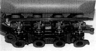
Fig. 6-17. An example of a carbureted intake manifold converted to EFI on the Maserati Bora.
Will a turbo work with my stock carburetor or stock fuel injection ?
stock carb: no
stock fuel injection: no, not quite
No fuel injection in use today will automatically provide fuel For the increased airflow created by the turbo. However, stock electronic fuel injection systems work so well in all nonboost modes that it is advisable to retain the system and keep it absolutely stock, for ease of repair.
What constitutes a proper intake manifold?
Streamlining, above all. Uniform port shapes, smooth section changes, and insulation from heat. Symmetry and runner length are important.
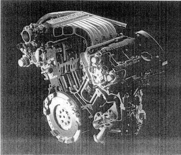
Fig. 6-18. The strong benefits of a good intake manifold design for turbo applications have prompted many people to create interesting and complex designs, such as the one made for this Mitsubishi 3-liter V-6 with twin turbos and intercoolers.
|
Politica de confidentialitate | Termeni si conditii de utilizare |

Vizualizari: 6226
Importanta: ![]()
Termeni si conditii de utilizare | Contact
© SCRIGROUP 2026 . All rights reserved