| CATEGORII DOCUMENTE |
| Bulgara | Ceha slovaca | Croata | Engleza | Estona | Finlandeza | Franceza |
| Germana | Italiana | Letona | Lituaniana | Maghiara | Olandeza | Poloneza |
| Sarba | Slovena | Spaniola | Suedeza | Turca | Ucraineana |
Safety Related Control Systems
First of all, what is a safety related control system (often abbreviated to SRCS)?
It is that part of the control system of a machine which prevents a hazardous condition from occurring. It can be a separate dedicated system or it may be integrated with the normal machine control system.
Its complexity will vary from a typical simple system, such as a guard door interlock switch and emergency stop switch connected in series to the control coil of power contactor, to a compound system comprising both simple and complex devices communicating through software and hardware.
In order to provide the safety function the system must continue to operate correctly under all foreseeable conditions.
So how do we design a system to achieve this, and when we have done that, how do we show it?
The European Standard prEN 954-1 'Safety related parts of control systems' deals with these aspects.
It lays down a 'language' of five categories for benchmarking and describing the performance of SRCSs.
Table 32 is a summary of the categories.
|
SUMMARY OF REQUIREMENTS |
SYSTEM BAHAVIOR |
PRINCIPLE |
|
CATEGORY B (See note 1) -Safety related parts of a machine control systems and/or their protective equipment, as well as their components, shall be designed, constructed, selected, assembled and combined in accordance with relevant standards so that they can withstand the expected influence. |
When a fault occurs it can lead to a loss of the safety function. |
By selection of components (Towards PREVENTION of faults) |
|
CATEGORY 1 -The requirements of category B apply together with the use of well tried safety components and safety principles. |
As described for category B but with higher safety related reliability of the safety related function. (The higher the reliability, the less the likelyhood of a fault.) |
By selection of components (Towards PREVENTION of faults) |
|
CATEGORY 2 -The requirements of category B and the use of well tried safety principles apply. -The safety function(s) shall be checked at machine start-up and periodically by the machine control system. If a fault is detected a safe state shall be initiated or if this is not possible a warning shall be given. |
The loss of a safety function is detected by the check. The occurrence of a fault can lead to the loss of safety function between the checking intervals. |
By structure (Towards DETECTION of faults) |
|
CATEGORY 3 (see notes 2 & 3) -The requirements of category B and the use of well tried safety principles apply. -the system shall be designed so that a single fault in any of its parts does not lead to the loss of a safety function. |
When the single fault occurs the safety function is always performed Some but not all faults will be detected An accumulation of undetected faults can lead to the loss of safety function |
By structure (Towards DETECTION of faults) |
|
CATEGORY 4 (see notes 2 & 3) -The requirements of category B and the use of well tried safety principles apply. -The system shall be designed so that a single fault in any of its parts does not lead to the loss of safety function. -The single fault is detected at or before the next demand on the safety function. If this detection is not possible then an accumulation of faults shall not lead to a loss of safety function. |
When the faults occur the safety function is always performed. The faults will be detected in time to prevent the loss of safety functions. |
By structure (Towards DETECTION of faults) |
Table 32
Note 1: Category B in itself has no special measures for safety but it forms the base for other categories.
Note 2: Multiple faults caused by a common cause or as inevitable consequences of the first fault shall be counted as a single fault.
Note 3: The fault review may be limited to two faults in combination if it can be justified but complex circuits (e.g. microprocessor circuits) may require more faults in combination to be considered.
In order to translate these requirements into a system design specification there has to be an interpretation of the basic requirements.
First of all let us dispose of one popular misconception. It is a commonly held belief that category 1 gives the least protection and category 4 gives the best. This is not the reasoning behind the categories. They are intended as reference points which describe the functional performance of different method types of safety related control systems (or their constituent parts).
Category 1 is aimed at the PREVENTION of faults. It is achieved by the use of suitable design principles, components and materials. Simplicity of principle and design together with the use of materials with stable and predictable characteristics are the keys to this category.
Categories 2, 3 and 4 require that if faults cannot be prevented they must be DETECTED (and appropriate action taken). Monitoring and checking are the keys to these categories. The most usual (but not the only) method of monitoring is to duplicate the safety critical functions (i.e. redundancy) and compare their operation.
Perhaps the best way to make further progress is to use examples.
The example in fig. 33 is a simple system comprising a guard door interlock switch connected in series to the control coil of a power contactor.
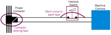 Fig.
33
Fig.
33
If we consider that the aim is toward complete reliability with no possibility of a failure to a dangerous condition, which of the categories is most appropriate?
Figure 33 also shows the location and nature of potential dangerous faults.
If we refer to table 32 which type of category is the most appropriate? The prevention of faults or the detection of faults?
The first step is to separate the system into its major components and consider their modes of potential failure.
In this example the components are:
• Interlock switch
• Contactor
• Wiring
The interlock switch is a mechanical device. The task which it performs is a simple one i.e. opening the contacts when a guard door is opened. It fulfills the requirements of category 1 and by the use of correct design principles and materials it can be proved that, when used within its stated operating parameters, it will have no failures to a dangerous condition. This is made feasible by the fact that the device is relatively simple and has predictable and provable characteristics.
The contactor is a slightly more complex device and may have some theoretical possibilities for failure. Contactors from reputable manufacturers are extremely reliable devices. Statistics show that failures are rare and can usually be attributed to poor installation or maintenance.
Contactors should always have their power contacts protected by an overcurrent cut-out device to prevent welding.
Contactors should be subject to a regular inspection routine to detect excessive contact pitting or loose connections which can lead to overheating and distortion.
The contactor should comply with relevant standards which cover the required characteristics and conditions of use.
By attending to these factors it is possible to keep the possibilities of failure to a minimum. But for some situations even this is unacceptable and in order to increase the level of safety provision we need to use duplication and monitoring.
The wiring which connects the components together must also be considered. Undetected short circuit and ground faults could lead to a dangerous condition but if it is properly designed and installed using standards such as EN 60204 for guidance then the chances of failure are greatly reduced.
This system can provide a significant level of safety which may be adequate for many situations. You may have noticed however that both the contactor and the wiring are prone to unlikely though theoretically foreseeable faults. In some cases it may be possible, by taking precautions (e.g. with regard to cable protection and routing) to eliminate all fault possibilities. If this is not feasible then techniques relevant to categories 2, 3 & 4 such as duplication and monitoring are usually both more practical and cost effective.
Fig. 34 shows a system which fulfills the requirements of category 3. An SR06AM safety monitoring relay unit is used to monitor a two channel control circuit. Any single fault on the wiring or contactors will be detected by the safety monitoring relay at the next demand on the safety function. NOTE: Although the interlock switch now has double pole contacts it is still a device which fulfills the requirements of category 1 - forming part of a system which fulfills the requirements of category 3.
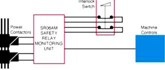 Fig.
34
Fig.
34
This poses the inevitable question of when, and to what degree, do we need to take such measures.
The simple answer is to say that it depends on the results of the risk assessment. This is the correct approach but we must understand that this includes all factors and not just the level of risk at the hazard point. For example, it may be thought that if the risk estimation shows a high level of risk, the interlock switch should be doubled up and monitored. But in many circumstances this device, due to its application, design and simplicity, will not fail to danger and there will be no undetected faults to monitor.
Therefore the situation is becoming clear, the type of category used will depend on both the risk assessment and the nature and complexity of the device or system. It is also clear that where a total system meets the requirements of category 3 for example it may include devices to category 1.
If there are fault possibilities the higher the degree of risk, obtained at the risk estimation, the greater the justification for measures to prevent or detect them and the type of category should be chosen to give the most suitable and efficient method of doing this. Remember, the level of risk estimate is one factor but the nature of the protective device or system and the machine's operating characteristics must also be taken into account.
Fig. 35 shows the same basic circuit but the interlock switch is
replaced by a safety light curtain. The
safety light curtain is a complex device. Even in its simplest form it will
have a relatively large number of electronic components including integrated
circuits. More sophisticated types (and
hence with more features) may also depend on programmable devices and software.
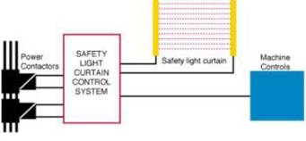 Fig.
35
Fig.
35
To anticipate and eliminate all dangerous faults in an electronic but non-programmable device would be a huge task and with a programmable device it would be virtually impossible. Therefore we must accept that faults will be possible and the best answer is to detect them and ensure that the necessary protective action is taken (e.g. locking out to a safe state). So we would need a device that satisfies the requirements of category 2, 3 or 4. With a simple circuit such as in fig. 35 the light curtain will also monitor the wiring and contactors. As all light curtains are relatively complex, the choice of categories will usually depend solely on the results of the risk assessment. This does not preclude the fact that it may be possible to work to a different category if a device uses an unconventional but provable approach. We can see from the last two examples that the same degree of protection is provided by two types of systems using devices satisfying different categories.
Hopefully these examples will encourage a pattern of logic to enable the correct decision to be made.
In this section we shall give examples of safety related control circuits with reference to recommended practices and the safety related control system categories where appropriate.
General Requirements
The system must be capable of withstanding all expected influences. These will include temperature, environment, power loading, frequency of use, airborne interference, vibration etc. The standard EN 60204-1 'Safety of machinery - Electrical equipment of machines – Specification for general requirements' provides detailed guidance on such things as electric shock protection, wiring practices, insulation, equipment, power supplies, control circuits and functions, etc. A knowledge of this standard is essential for those concerned with the design and maintenance of safety related control systems.
The examples given below are based on the use of a control interlocking switch but the same principle can be applied to other switching device e.g. emergency stop or trip devices.
Fig. 36 shows a simple safety related control circuit. The
interlock device has positive mode operation and satisfies the requirements of
category 1. The contactor is correctly selected for its duty and is designed
and manufactured to specific standards. The part of the system most prone to a
fault is the connecting wiring. In order to overcome this it should be
installed in accordance with the relevant clauses of standard EN 60204. It
should be routed and protected in a manner which prevents any foreseeable short
circuits or earth faults. This system will satisfy the requirements of category
1. 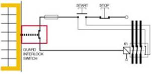 Fig.
36
Fig.
36
Fig. 37 shows a slightly more complex circuit. In this case there is a requirement for the interlock device to control more than one contactor, each being on a different power circuit. Its component parts must be given the same considerations.
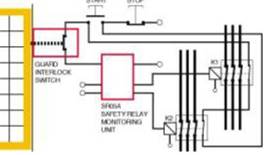 Fig.
37
Fig.
37
With a non-safety related circuit an ordinary relay could be used to 'split' the signal but where safety is concerned this would definitely not be acceptable as they can (and sometimes do) stick. Therefore a monitoring safety relay unit such as the SR05A is used to provide an ensured switching action. This system will satisfy the requirements of category 1.
Fig. 38 shows a system which satisfies the requirements of
category 2 and therefore must undergo a test of the safety function before the
machine can be started. It must also be tested periodically. At initial power
up the safety monitoring relay will not allow switching of power to the
contactor until the guard is opened and closed. ThisFig.
36
Fig. 37 shows a slightly more complex circuit. In this case there is a requirement for the interlock device to control more than one contactor, each being on a different power circuit. Its component parts must be given the same considerations.
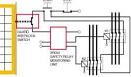 Fig.
37
Fig.
37
With a non-safety related circuit an ordinary relay could be used to 'split' the signal but where safety is concerned this would definitely not be acceptable as they can (and sometimes do) stick. Therefore a monitoring safety relay unit such as the SR05A is used to provide an ensured switching action. This system will satisfy the requirements of category 1.
Fig. 38 shows a system which satisfies the requirements of category 2 and therefore must undergo a test of the safety function before the machine can be started. It must also be tested periodically. At initial power up the safety monitoring relay will not allow switching of power to the contactor until the guard is opened and closed. This initiates a check for any single faults in the circuit from the switch to the safety monitoring relay. Only when this check is successful will the contactor be energized. At every subsequent guard operation the circuit will be similarly checked.
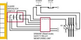 Fig.
38
Fig.
38
Fig. 39 shows a system which satisfies the requirements of category 3 and is often suitable for applications with higher risk estimations. It is a dual channel system which is fully monitored including the two contactors. On opening and closing the guard, any single dangerous fault will cause the safety monitoring relay to lock off power to the contactors until the fault is rectified and the safety monitoring relay is reset.
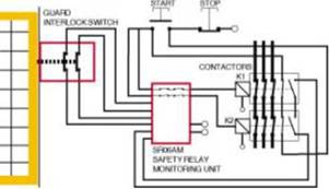 Fig.
39
Fig.
39
Category 4 requires that the safety system function is still provided even with an accumulation of undetected faults. The most practicable way of achieving this is to employ continuous or high frequency monitoring techniques. This is not feasible with most mechanical or electromechanical components (e.g. mechanical switches, relays, contactors) such as are used in interlocking and emergency stop systems.
These techniques are viable (and often used) to monitor solid state electronic components because a high frequency changing of state is possible and does not substantially degrade the life of the component. Therefore the category 4 approach is often found in self contained 'sub-systems' such as light curtains.
P.E.S. (Programmable Electronic Systems)
In the safety related circuits shown previously, the protective device is directly connected to the contactor(s) using only wiring and simple or fully monitored electromechanical devices. This is the normally recommended 'hard wired' method. Its simplicity means that it is reliable and relatively easy to monitor.
Increasingly the normal operational control of machinery is being handled by programmable equipment. With the advances in technology, programmable and complex electronic control systems could be regarded as the central nervous system of many machines. Whatever happens in the control system will affect the machine action and conversely whatever happens to the machine action will affect the control system. Stopping one of these machines by any source other than its control system may result in severe tool and machine damage as well as program loss or damage. It is also possible that, upon restarting, the machine may behave in an unpredictable manner due to 'scrambling' of its control command sequence.
Unfortunately most programmable electronic systems have too many failure modes due to their complexity to allow their use as the only way of stopping the machine on command from an guard door interlock or emergency stop button. In other words we can stop it without machine damage OR stop it SAFELY BUT NOT BOTH. So what do we do? Three solutions are given below:
1 - Safety Related Programmable Systems
In theory it is possible to design a programmable system which has a safety integrity level high enough for safety related use. In practice this would normally be achieved by using special measures such as duplication and diversity with cross monitoring. In some situations this may be possible but it is important to realize that these special measures will need to be applied to all aspects including the writing of software.
The basic question is, can you prove that there will be no (or sufficiently few) failures. A full failure mode analysis for even relatively simple programmable equipment may, at best, be excessively time consuming and expensive or, at worst, be impossible.
The standard IEC1508 deals with this subject in great detail. Anyone concerned with safety related programmable systems is advised to study it.
The development costs of these systems are justifiable in applications where they have significant advantages or no other method will work.
2 - Monitoring Unit with Time Delayed Override Command (see Fig. 40)
This system has the high integrity level of hard wiring and also allows a correctly sequenced shut-down which protects the machine and program.
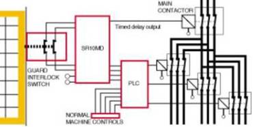 Fig.
40
Fig.
40
The SR10MD primary outputs are connected to inputs at the programmable device (e.g. PLC) and the delayed outputs are connected to the contactor. When the guard interlock switch is actuated, the primary outputs on the safety monitoring relay switch immediately. This signals the programmable system to carry out a correctly sequenced stop. After sufficient time has elapsed to allow this process the delayed output on the safety monitoring relay switches and isolates the main contactor.
This range of safety monitoring relays can be used with various protective devices and is avail-able with other configurations and switching arrangements to suit the requirements of particular systems.
Note: Any calculations to determine the overall stopping time must take account of the safety monitoring relay output delay period. This is particularly important when using this factor to determine the positioning of devices in accordance with standard pr EN 999.
3 - Programmable System Controlled Guard Locking Devices (see Fig. 41)
This system again provides the high integrity level of hard wiring combined with the ability to give a correctly sequenced shut down but it is only applicable where the hazard is protected by a guard.
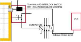 Fig.
41
Fig.
41
In order to allow opening of the guard door the TL8018 solenoid must receive a release signal from the PLC. This signal will only be given after a stop command sequence has been completed. This ensures there is no tool damage or program loss. When the solenoid is energized the door can be opened which causes the control circuit contacts on the TL8018 to isolate the machine contactor.
To overcome machine run-down or spurious release signals, it may be necessary to use an STI SMT01 timed delay unit or SMD02 stopped motion detector in conjunction with the PLC. (Either the TL8018 or TL8012 switches can be used in this application.)
Other Considerations
Machine Restart - Manual/ Auto Reset and Control Guards
If (for example) an interlocked guard is opened on an operating
machine, the safety interlock switch will stop that machine. In most
circumstances it is imperative that the machine does not restart immediately
when the guard is closed. The most common way of achieving this is to rely on a
latching contactor start arrangement as shown in Fig. 42 (an interlocked guard
door is used as an example here but the requirements apply to other protection
devices and emergency stop systems). 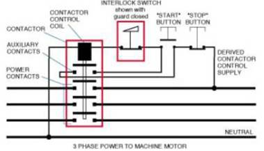 Fig.
42
Fig.
42
Pressing and releasing the start button momentarily energizes the contactor control coil which closes the power contacts. As long as power is flowing through the power contacts the control coil is kept energized (electrically latched) via the contactor's auxiliary contacts which are mechanically linked to the power contacts. Any interruption to the main power or control supply results in the de-energizing of the coil and opening of the main power and auxiliary contacts. The guard interlock is wired into the contactor control circuit. This means that restart can only be achieved by closing the guard and then switching 'ON' at the normal start button which resets the contactor and starts the machine.
The requirement for normal interlocking situations is made clear in EN 292 part 1 3.22.4
When the guard is closed, the hazardous machine functions covered by the guard can operate, but the closure of the guard does not by itself initiate their operation.
Many machines already have either single or double contactors which operate as described above (or have a system which achieves the same result). When fitting an interlock to existing machinery it is necessary to determine whether the power control arrangement meets this requirement and take additional measures if necessary.
On some types of protective devices, after actuation of the safety function, the output will remain off until the device has been reset.
Some devices are available in either manual reset or auto-reset versions.
A manual reset depends on a manual switching action after thede-actuation of the device and may also trigger a system integrity check before the safety system is reset to render the machine capable of being started. It will require the operation of a button or key operated switch which may be fitted either on the device, the control unit or at a remote location. Wherever it is, it should provide a good view of the hazard so that the operator can check that the area is clear before operation.
In Fig. 43, after the guard has been opened and closed again the safety monitoring relay will not allow the machine to be restarted until the reset button has been pressed and released. When this is done the safety monitoring relay checks that both contactors are OFF and that both interlock circuits (and therefore the guard) are closed. If these checks are successful the machine can then be restarted from the normal controls.
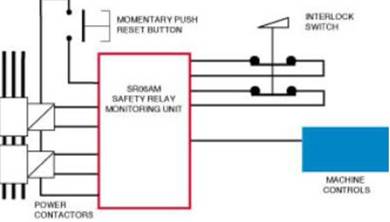 Fig.
43
Fig.
43
An auto-reset device does not require a manual switching action but after de-actuation it will always conduct a system integrity check before resetting the system. An auto-reset system should not be confused with a device without reset facilities. In the latter the safety system will be enabled immediately after de-actuation but there will be no system integrity check.
A control guard stops a machine when the guard is opened and directly starts it again when the guard is closed.
The use of control guards is only allowed under certain stringent conditions because any unexpected start-up or failure to stop would be extremely dangerous. The interlocking system must have the highest possible reliability (it is often advisable to use guard locking).
The use of control guards can ONLY be considered on machinery where there is NO POSSIBILITY of an operator or part of his body staying in or reaching into the danger zone while the guard is closed.
The control guard must be the only access to the hazard area.
Control reliability
is defined by ANSI standard B11.19-1990, 5.5 as '…the device, system or
interface shall be designed, constructed and installed such that a single
component failure within the device, interface or system shall not prevent
normal stopping action from taking place but shall prevent a successive machine
cycle…' This definition is accepted
for use in the
|
Politica de confidentialitate | Termeni si conditii de utilizare |

Vizualizari: 508
Importanta: ![]()
Termeni si conditii de utilizare | Contact
© SCRIGROUP 2025 . All rights reserved