| CATEGORII DOCUMENTE |
| Bulgara | Ceha slovaca | Croata | Engleza | Estona | Finlandeza | Franceza |
| Germana | Italiana | Letona | Lituaniana | Maghiara | Olandeza | Poloneza |
| Sarba | Slovena | Spaniola | Suedeza | Turca | Ucraineana |
Three-Phase Transformers
Since most of the power generated and transmitted over long distances is of the three-phase type, we can use three exactly alike single-phase transformers to form a single three-phase transformer. For economic reasons, however, a three-phase transformer is designed to have all six windings on a common magnetic core. A common magnetic core, three-phase transformer can also be either a core type (Figure 1.35) or a shell type (Figure 1.36).
Since the third harmonic flux created by each winding is in phase, a shell-type transformer is preferred because it provides an external path for this flux. In other words, the voltage waveforms are less distorted for a shell-type transformer than for a core-type transformer of similar ratings.
The three windings on either side of a three-phase transformer can be connected either in wye (Y) or in delta (D). Therefore, a three-phase transformer can be connected in four possible ways: Y/Y, Y/D D/Y, and D D. Some of the advantages and drawbacks of each connection are highlighted below.
Y/Y Connection
A Y/Y connection for the primary and secondary windings
of a three-phase transformer is depicted in Figure 1.37. The line-to-line
voltage on each side of the three-phase transformer is ![]() times the nominal
voltage of the single-phase transformer. The main advantage of a Y/Y connection
is that we have access to the neutral terminal on each side and it can be
grounded if desired. Without grounding the neutral terminals, the Y/Y operation
is satisfactory only when the three-phase load is balanced. The electrical
insulation is stressed only to about 58% of the line voltage in a Y-connected
transformer.
times the nominal
voltage of the single-phase transformer. The main advantage of a Y/Y connection
is that we have access to the neutral terminal on each side and it can be
grounded if desired. Without grounding the neutral terminals, the Y/Y operation
is satisfactory only when the three-phase load is balanced. The electrical
insulation is stressed only to about 58% of the line voltage in a Y-connected
transformer.
Since most of the transformers are designed to operate at or above the knee of the curve, such a design causes the induced emfs and currents to be distorted. The reason is as follows: Although the excitation currents are still 120o out of phase with respect to each other, their waveforms are no more sinusoidal. These currents, therefore, do not add up to zero. If the neutral is not grounded, these currents are forced to add up to zero. Thus, they affect the waveforms of the induced emfs.
D D Connection
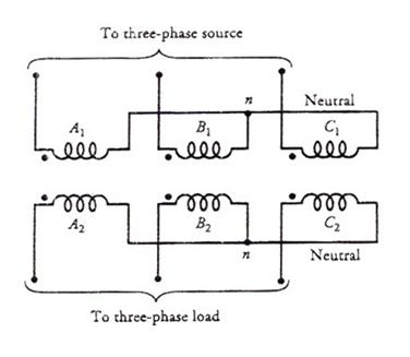
Figure 1.37 A Y/Y-connected three- phase transformer.
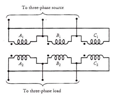
Figure 1.38 A D D-connected three-phase transformer.
Figure 1.38 shows the three transformers with the primary and secondary windings connected as D D. The line-to-line voltage on either side is equal to the corresponding phase voltage. Therefore, this arrangement is useful when the voltages are not very high. The advantage of this connection is that even under unbalanced loads the three-phase load voltages remain substantially equal. The disadvantage of the D D-connection is the absence of a neutral terminal on either side. Another drawback is that the electrical insulation is stressed to the line voltage. Therefore, a D-connected winding requires more expensive insulation that a Y-connected winding for the same power rating.
A D D-connection can be analyzed theoretically by transforming it into a simulated Y/Y connection using D-to-Y transformations.
Y/D Connection
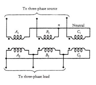
Figure 1.39 A Y/D-connected three-phase transformer.
This connection, as shown in Figure 1.39, is very suitable for step-down applications. The secondary winding current is about 58% of the load current. On the primary side the voltages are form line to neutral, whereas the voltages are from line to line on the secondary side.
Therefore, the voltage and the current in the primary are out of phase the voltage and the current in the secondary. In a Y/D connection, the distortion in the waveform of the induced voltages is not as drastic as it is in a Y/Y- connected transformer when the neutral is not connected to the ground. The reason is that the distorted currents in the primary give rise to a circulating current in the D- connected secondary. The circulating current acts more like a magnetizing current and tends to correct the distortion.
D/Y Connection
This connection, as depicted in Figure 4.40, is proper for a step-up application. However, this connection is now being exploited to satisfy the requirements of both the three-phase and the single-phase loads. In this case, we use a four-wire secondary. The single-phase loads are taken care of by the three line-to-neutral circuits. An attempt is invariably made to distribute the single-phase loads almost equally among the three phases.
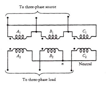
Figure 1.40 A D/Y-connected three-phase transformer.
Analysis of a Three-Phase Transformer
Under steady-state conditions, a single three-phase transformer operates exactly the same way as three single-phase transformers connected together. Therefore, in our discussion that follows we assume that we have three identical single-phase transformers connected to form a three-phase transformer. Such an understanding helps us to develop the per-phase equivalent circuit of a three- phase transformer.
We also assume that the three-phase transformer delivers a balanced load, and the waveforms of the induced emfs are purely sinusoidal. In other words, the magnetizing currents are not distorted and there are no third harmonics.
We can analyze a three-phase
transformer in the same way we have analyzed a three-phase circuit. That is, we
can employ the per-phase equivalent circuit of a transformer. A D-connected winding of a three-phase
transformer can be replaced by an equivalent Y-connected winding using D-to-Y transformation. If ![]() is the impedance in a D-connected winding, the equivalent impedance
is the impedance in a D-connected winding, the equivalent impedance ![]() in a Y-connected winding is
in a Y-connected winding is
 (1.42)
On the other hand, if ![]() is the line-to-line
voltage in a Y-connected winding the line-to-neutral voltage
is the line-to-line
voltage in a Y-connected winding the line-to-neutral voltage ![]() is
is
 (1.43)
where the plus sign is for the negative phase-sequence (counterclockwise) and the minus sign is for the positive phase-sequence (clockwise).
The following examples show how to analyze a system of balanced three-phase transformers. Unless it is specified otherwise, we assume that the impressed voltages on the primary side follow the positive phase-sequence.
|
Politica de confidentialitate | Termeni si conditii de utilizare |

Vizualizari: 1272
Importanta: ![]()
Termeni si conditii de utilizare | Contact
© SCRIGROUP 2025 . All rights reserved