| CATEGORII DOCUMENTE |
| Bulgara | Ceha slovaca | Croata | Engleza | Estona | Finlandeza | Franceza |
| Germana | Italiana | Letona | Lituaniana | Maghiara | Olandeza | Poloneza |
| Sarba | Slovena | Spaniola | Suedeza | Turca | Ucraineana |
SYNCHRONOUS GENERATOR
1 Introduction
Alternating-current (ac) generators are commonly referred to as synchronous generators or alternators. A synchronous machine, whether it is a generator or a motor, operates as synchronous speed, that is, at the speed at which the magnetic field created by the field coils rotates.
We have already elaborated this fact in past sections and obtained an expression for the synchronous speed Ns in revolutions per minute (rpm) as
 (1)
(1)
where f is the frequency in hertz (Hz) and P is the number of poles in the machine.
Thus, for a 4-pole synchronous generator to generate power at 60 Hz, its speed of rotation must be 1800 rpm. On the other hand, a 4-pole synchronous motor operating from a 50-Hz source runs at only 1500 rpm. Any attempt to overload the synchronous motor may pull it out of synchronism and force it to stop.
During our discussion of a direct-current (dc) generator we realized that the electromotive force (emf) induced in its armature coils is of the alternating type. Therefore, we can convert a dc generator to an ac generator by
(a) replacing its commutator with a set of slip rings and
(b) rotating the armature at a constant (synchronous) speed.
The idea is novel but is not put into practice for the reasons we will mention shortly.
We also recall that the relative motion of a conductor with respect to the magnetic flux in a machine is responsible for the induced emf in that conductor.
In other words, from the induced emf point of view it really does not matter whether the conductors (coils) rotate in a stationary magnetic field or a rotating magnetic field links a stationary conductor (coil). The former arrangement is preferred for dc generators and was discussed , whereas the latter is more suitable for synchronous generators and is the topic of this chapter. Thus, the stationary member (stator) of a synchronous generator is commissioned as an armature, and the rotating member (rotor) carries the field winding to provide the required flux.
There are numerous reasons for such an inside-out construction of a synchronous generator, some of which are listed below.
Most synchronous generators are built in much larger sizes than their dc counterparts. An increase in power capacity of a generator requires thicker conductors in its armature winding to carry high currents and to minimize copper losses. Deeper slots are therefore needed to house thicker conductors. Because the stator can be made large enough with fewer limitations, it inadvertently becomes the preferred member to house the armature conductors.
Since the output of a synchronous generator is of the alternating type, the armature conductors in the stator can be directly connected to the transmission line. This eliminates the need for slip rings for ac power output.
Since most of the heat is produced by the armature winding, an outer stationary member can be cooled more efficiently than an inner rotating member.
Since the armature winding of a synchronous machine is more involved than the field winding, it is easier to construct it on the stationary member.
Since the induced emf in the armature winding is quite high, it is easier to insulate it when it is wound inside the stationary member rather than the rotating member. A rigid frame also enables us to brace the armature winding more securely.
The placement of a low-power field winding on the rotor presents no deterrent to the inside-out construction of a synchronous generator. The power to the field winding can be supplied via slip rings. If the field is supplied by permanent magnets, the slip rings can also be dispensed with.
2 Construction of a Synchronous Machine
The basic components of a synchronous machine are the stator, which houses the armature conductors, and a rotor, which provides the necessary field as outlined below.
Stator
The stator, also known as the armature, of a synchronous machine is made of thin laminations of highly permeable steel in order to reduce the core losses.
The stator laminations are held together by a stator frame. The frame may be of cast iron or fabricated from mild steel plates. The frame is designed not to carry the flux but to provide mechanical support to the synchronous generator.
The inside of the stator has a plurality of slots that are intended to accommodate thick armature conductors (coils or windings). The armature conductors are symmetrically arranged to form a balanced polyphase winding. To this end, the number of slots per pole per phase must be an integer. The induced emf per phase in large synchronous generators is in kilovolts (kV) with a power handling capacity in megavolt-amperes (MVA).
The axial length of the stator core is comparatively short for slow-speed, large-diameter generators. These generators have many poles and are left open on both ends for self-cooling. They are installed at locations where hydroelectric power generation is possible.
 The axial length of high-speed generators having 2 or 4
poles can be many times its diameter. These generators require forced air
circulation for cooling and are totally enclosed. They are used when the rotors
are driven by gas or steam turbines.
The axial length of high-speed generators having 2 or 4
poles can be many times its diameter. These generators require forced air
circulation for cooling and are totally enclosed. They are used when the rotors
are driven by gas or steam turbines.
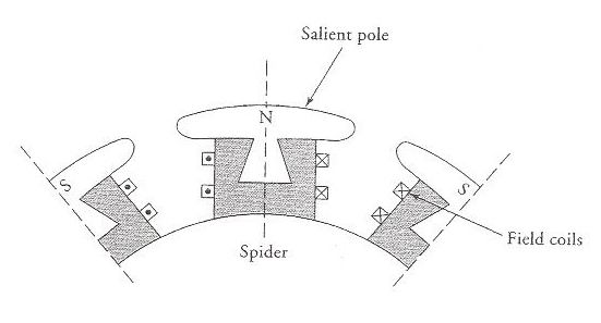
Figure 1 A salient pole rotor.
Rotor
Two types of rotors are used in the design of synchronous generators, the cylindrical rotor and a salient-pole rotor. The rotor is rotated at the synchronous speed by a prime mover such as a steam turbine. The rotor has as many poles as the stator, and the rotor winding carries dc current so as to produce constant flux per pole.
The filed winding usually receives its power from a 115- or 230-V dc generator. The dc generator may be driven either by the same prime mover driving the synchronous generator or by a separate electric motor.
The salient-pole rotor is used in low- and medium-speed generators because the windage loss is small at these speeds. It consists of an even set of outward projecting laminated poles.
Each pole is dovetailed so that it fits into a wedge-shaped recess or is bolted onto a magnetic wheel called the spider. The field winding is placed around each pole, as indicated in Figure 1. The poles must alternate in polarity.
The cylindrical rotor is employed in a 2- or 4-pole, high-speed turbo-generator. It is made of a smooth solid forged steel cylinder with a number of slots on its outer periphery. These slots are designed to accommodate the field coils, as shown in Figure 2. The cylindrical construction offers the following benefits:
It results in a quiet operation at high speed.
It provides better balance than the salient-pole rotor.
It reduces the windage loss.
3 Armature Windings
The stators (armatures) of most synchronous generators are wound with three distinct and independent windings to generate three-phase power. Each winding is said to represent one phase of a three-phase generator.
The three windings are exactly alike in shape and form but are displaced from each other by exactly 120o electrical in order to ensure that the induced emfs in these windings are exactly 120o in time phase.
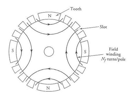
Figure 2 A 4-pole cylindrical rotor.
The three-phase windings may be connected to form either a star (Y) or a delta (D) connection. If the windings are internally connected to form a Y connection, the neutral point is also brought out so that it can be properly grounded for safe operation.
The double-layer winding is often used to wind the armature of a synchronous generator. As you may recall, a double-layer winding requires as many identical coils as there are slots in the stator. One side of each coil is placed at the bottom half of a slot, and the other side of the same coil fills the top half of another slot. In order to place the coils in this fashion, the coils must be prewound on the winding forms and then inserted into the slots.
The number of coils per phase (or the number of slots per phase for a double-layer winding) must be an integer. Since the coils must be distributed equally among the poles, the number of coils (slots) per pole per phase must also be an integer. In other words, if S is the number of slots in the armature, P is the number of poles, and q is the number of phases, then the number of coils per pole per phase is
 (2)
(2)
where n must be an integer. The number of coils per pole per phase, n, is usually referred to as a phase group or phase belt. When the stator of a three-phase, 4-pole synchronous generator has 24 slots, the number of coils in each phase group is 2. There are 12 phase groups (poles x phases). All coils in a phase group (2 in this case) are connected in series.
Each coil in a phase group can be wound as a full-pitch coil. In other words, each coil in the armature can be made to span 180o electrical. Since the induced emfs in both sides of a full-pitch coil at any time are exactly in phase, theoretical yearning mandates the placement of full-pitch coils from the induced emf point of view. However, a full-pitch coil is rarely used. Instead, the generators are wound with fractional-pitch coils for the following reasons:
A properly designed fractional-pitch coil reduces the distorting harmonics and produces a truer sinusoidal waveform.
A fractional-pitch coil shortens the end connections of the windings and thereby not only saves copper but also reduces the copper loss in the coil.
A shorter coil is easier to manage and reduces the end-turn build-up on both sides of the stators stack. This slims down the overall length of the generator and minimizes the flux leakages.
The elimination of high-frequency harmonics also cuts down the magnetic losses in the generator.
The drawback of a fractional-pitch coil is that the induced emf in it is smaller than in a full-pitch coil. The reason is that the total flux linking the fractional-pitch coil is smaller than that of the full-pitch coil. The ration of the flux linking the fractional pitch coil to the flux that would link a full-pitch coil is called the pitch factor. Later, we will develop an equation to determine the pitch factor.
To illustrate the placement of the phase windings in the slots of a synchronous generator, we make the following assumptions:
(a) All coils are identical.
(b) Each coil is a fractional-pitch coil as long as a phase group contains more than one coil. All the coils in a phase group are connected in series.
(c) Each phase group spans 180o electrical (one full pitch). Thus, the n coils in a phase group must be placed in such a way that the beginning end of the first coil is under the beginning of a pole and the finishing end of the nth coil is under the trailing end of the pole.
The electrical angle from the center of one slot to the center of an adjacent slot is known as the slot span or slot pitch. The coil span or coil pitch, the number of slots spanned by each coil, can be expressed in terms of either electrical degrees of the number of slots, as illustrated by the following example.
7 Induced emf Equation
Let us assume that the total flux emanating per pole of a round rotor revolving at an angular velocity of ws is Fp. The maximum flux linking the fractional pitch coil is Fp kp where kp = sin (r/2) is the pitch factor and r is the coil span in electrical degrees. As the flux revolves, the flux linking the coil at any time t can be expressed as
![]() (10)
(10)
where w pf is the angular frequency in rad/s.
For a coil with Nc turns, the induced emf in the coil, from Faradays law is
![]() (11)
(11)
The maximum value of the induced emf is
![]() (12)
(12)
and its rms value is
 (13)
(13)
where
the factor ![]() has been approximated
as 4.44
has been approximated
as 4.44
Since a phase group usually has more than one coil connected in series and each coil is displaced by a slot pitch, the induced emf in the phase group, from Eq. (7), is
![]() (14)
(14)
where n is the number of coils in a phase group and kd is the distribution factor as given by Eq. (8). For a given generator, the product kpkd is constant and is referred to as the winding factor. That is, the winding factor, kw, is
![]() (15)
(15)
The rms value of the induced emf in each phase group can be expressed in terms of the winding factor as
![]() (16)
(16)
For a generator having P poles and a parallel paths, the induced emf per phase (phase voltage) is
 (17)
(17)
The factor PnNc/a in the above equation represents the actual number of turns per phase connected in series when there are a parallel paths. By taking into account the winding factor, kw, we can define the effective turns per phase as
 (18)
(18)
Finally, we obtain an expression for the per-phase (no-load) voltage as
![]() (19)
(19)
Note that Eq. (19) is very similar to the one obtained for a transformer. In the case of a transformer, the effective number of turns is the same as the actual number of turns because each transformer winding consists of one coil that embraces the total flux in the magnetic core. The winding factor for a synchronous generator could also have been unity if (a) we used a full-pitch coil and (b) all the coils in a phase group were placed in the same slots.
8 The Equivalent Circuit
During our discussion of dc generators, we discerned that the terminal voltage of a dc generator is smaller than the generated voltage owing to (a) the voltage drop across its armature winding and (b) the decrease in the armature flux caused by the armature reaction.
However, the terminal voltage of an ac generator depends upon the load and may be larger or smaller than the generated voltage. In fact, we aim to show that the terminal voltage may actually be higher than the generated voltage when the power factor (pf) is leading. For unity and lagging power factors, the terminal voltage is smaller than the generated voltage.
Armature Resistance Voltage Drop
Let ![]() be the per-phase
generated voltage of a synchronous generator and
be the per-phase
generated voltage of a synchronous generator and ![]() the per-phase current supplied by it to the load. If Ra is the per-phase
resistance of the armature winding, then
the per-phase current supplied by it to the load. If Ra is the per-phase
resistance of the armature winding, then ![]() is the voltage drop
across it. The
is the voltage drop
across it. The ![]() voltage drop is in
phase with the load current
voltage drop is in
phase with the load current ![]() . Since Ra
also causes a power loss in the generator, it is kept as small as possible,
especially for large machines.
. Since Ra
also causes a power loss in the generator, it is kept as small as possible,
especially for large machines.
Armature Leakage-Reactance Voltage Drop
The current ![]() in the armature
winding produces a flux. A part of the flux, the so-called leakage flux, links
the armature winding only and gives rise to a leakage reactance Xa. The leakage reactance
causes a voltage drop
in the armature
winding produces a flux. A part of the flux, the so-called leakage flux, links
the armature winding only and gives rise to a leakage reactance Xa. The leakage reactance
causes a voltage drop ![]() , which leads
, which leads ![]() by 90o. The
phasor diagrams depicting relationships between the per-phase generated voltage
by 90o. The
phasor diagrams depicting relationships between the per-phase generated voltage
![]() , the per-phase terminal voltage
, the per-phase terminal voltage ![]() , and the voltage drops
, and the voltage drops ![]() and
and ![]() for three types of
loads are shown in Figure 12.
for three types of
loads are shown in Figure 12.
Armature Reaction
The flux produced by the armature winding reacts with the flux set up by the poles on the rotor, causing the total flux to change. Such an interaction between the two fluxes is known as the armature reaction. To understand the effect of armature reaction on the terminal voltage of a synchronous generator, let us examine a sequence of events when the generator delivers a load at a unity power factor.
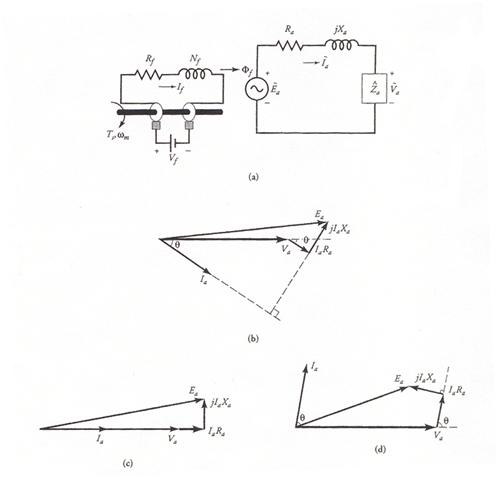
Figure 12 (a) The per-phase equivalent circuit of a synchronous generator without armature reaction while depicting the revolving field produced by the rotor. The phasor diagrams for a (b) lagging pf, (c) unity pf, and (d) leading pf.
(a) If Fp is the flux per pole in the generator under no load, then the generated voltage Ea must lag Fp by 90o, as shown in Figure 13.
(b) Since the
power factor is unity, the phase current ![]() is in phase with the
terminal phase voltage
is in phase with the
terminal phase voltage ![]() .
.
(c) As the phase
current ![]() passes through the
armature winding, its magnetomotive force (mmf) produces a flux Far which is in phase with
passes through the
armature winding, its magnetomotive force (mmf) produces a flux Far which is in phase with ![]() . The effective flux Fe per pole in the generator is the algebraic sum of
the two fluxes; that is, Fe Fp Far, as shown in the figure.
. The effective flux Fe per pole in the generator is the algebraic sum of
the two fluxes; that is, Fe Fp Far, as shown in the figure.
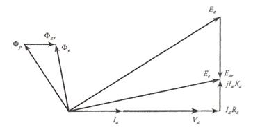
Figure 13 Phasor diagram depicting the effect of armature reaction when the power factor is unity.
(d) The flux Far, in turn, induces an emf ![]() in the armature winding.
in the armature winding. ![]() is called the armature
reaction emf. The armature reaction emf
is called the armature
reaction emf. The armature reaction emf ![]() lags the flux Far by 90o. Hence
the effective generated voltage per-phase
lags the flux Far by 90o. Hence
the effective generated voltage per-phase ![]() is the algebraic sum
of the no-load voltage
is the algebraic sum
of the no-load voltage ![]() and the armature reaction emf
and the armature reaction emf ![]() . That is,
. That is, ![]() An equivalent circuit
showing the armature reaction emf is given in Figure 14.
An equivalent circuit
showing the armature reaction emf is given in Figure 14.
(e) 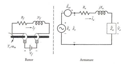
(f)
Figure 14 A per-phase equivalent circuit showing the induced emf in the armature winding due to the armature reaction.
(e) The per-phase terminal voltage ![]() is obtained by
subtracting the voltage drops
is obtained by
subtracting the voltage drops ![]() and
and ![]() from
from ![]() . In other words,
. In other words,
![]() (20)
(20)
From the phasor diagram, it should be obvious that the armature reaction has reduced the effective flux per pole when the power factor of the load is unity.
Also, the terminal voltage is smaller than the generated voltage.
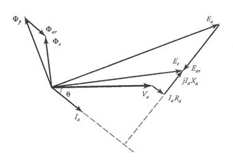
Figure 15 The phasor diagram showing the effect of armature reaction when the power factor is lagging.
By following the above sequence of
events, we can obtain the phasor diagrams for the lagging (Figure 15) and the
leading (Figure 16) power factors. From these figures it is evident that the
resultant flux is (smaller/larger) with armature reaction for the
(lagging/leading) power factor than without it. In addition, the terminal
voltage ![]() is (higher/lower) than
the generated voltage
is (higher/lower) than
the generated voltage ![]() when the power factor is (leading/ lagging). Since the flux
per pole Fp is different for each of the three load conditions,
the field current If must be adjusted each time the load is
changed.
when the power factor is (leading/ lagging). Since the flux
per pole Fp is different for each of the three load conditions,
the field current If must be adjusted each time the load is
changed.
Since the armature reaction emf ![]() lags the current
lags the current ![]() by 90o, we
can also express it as
by 90o, we
can also express it as
![]() (21)
(21)
where Xm, a constant of proportionality, is known as the magnetization reactance.
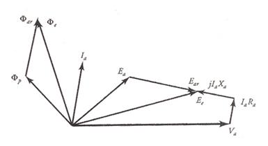
Figure 16 The phasor diagram showing the effect of armature reaction when the power factor of the load is leading.
Both the magnetization reactance and the leakage reactance are present at the same time. It is rather difficult to separate one reactance from the other. For this reason, the two reactances are combined together and the sum
![]() (22)
(22)
is called the synchronous reactance. The synchronous reactance is usually very large compared with the resistance of the armature winding. We can now define the synchronous impedance on a per-phase basis as
![]() (23)
(23)
The Equivalent Circuit and Phasor Diagrams
The exact equivalent circuit of a synchronous generator on a per-phase basis embodying the synchronous reactance is given in Figure 1 The per-phase terminal voltage is
![]() (24)
(24)
and the corresponding phasor diagrams for three types of loads are given in Figure 1
Voltage Regulation
The voltage regulation of a synchronous generator is defined as the ratio of the change in the terminal voltage from no load to full load to the full-load voltage. Since Ea is the no-load voltage and Va is the terminal voltage at full load, the percent voltage regulation is
 (25)
(25)
9 Power Relationships
The rotor of a synchronous generator is connected to a prime mover which may, in fact, be a dc motor, a steam turbine, a gas turbine, a diesel engine, or the like. If the prime mover exerts a torque Ts at the shaft at an angular velocity of ws, the mechanical power supplied to the rotor is Ts ws. Consequently, the mechanical power input to the generator is
 (26a)
(26a)
The dc power input to a wound rotor is Vf If , where Vf is the dc voltage across the field winding and If is the dc current through it. Thus, the total power input is
![]() (26b)
(26b)
The losses in a synchronous generator consist of rotational loss (mechanical loss and magnetic loss), the copper loss in the armature winding, the field-excitation loss in the field winding, and the stray-load loss, if any. We subtract the rotational loss, the field-winding loss, and the stray-load loss from the input power to obtain th power developed by the armature. By subtracting the cooper losses in the armature from the developed power, we obtain the output power of a synchronous generator, as illustrated by the power-flow diagram of Figure 18.
If Va is the per-phase load voltage, Ia is the per-phase load current, and q is the phase angle between Va and Ia, the power output of a synchronous generator is
![]() (27)
(27)
The copper loss in the armature winding is
![]() (28)
(28)
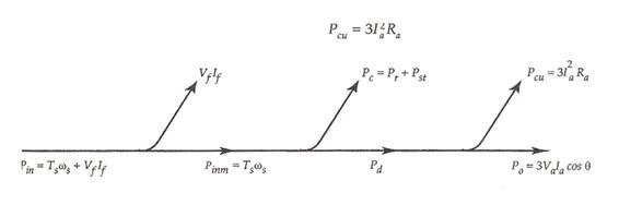
Figure 18 Power-flow diagram of a synchronous generator.
If Pr is the rotational loss of a synchronous generator and Pst is the stray-load loss, then the power input is
![]() (29)
(29)
Since the rotor revolves at a constant speed, the rotational loss is constant. The field-winding loss is constant. Assuming the stray-load loss to be a constant, we can group these losses together and treat them as a constant loss. Thus, the constant loss is
![]() (30)
(30)
Since the copper loss in the armature depends upon the load current, it is considered a variable loss.
The efficiency of the generator is
 (31)
(31)
From the above equation we obtain a condition for the maximum efficiency as
![]() (32)
(32)
Approximate Power Relationship
As mentioned earlier, the per-phase armature-winding
resistance of a synchronous generator is usually very small and can be
neglected in comparison with its synchronous reactance. The approximate
equivalent circuit and a corresponding phasor diagram for a lagging load are
given in Figure 19. Note that the terminal-phase voltage ![]() has been taken as a
reference and the per-phase generated voltage
has been taken as a
reference and the per-phase generated voltage ![]() leads
leads ![]() by an angle d. The phase current
by an angle d. The phase current ![]() lags
lags ![]() by an angle q. Thus,
by an angle q. Thus,
![]() (33)
(33)
and
![]() (34)
(34)
where
Ea and Ia are the rms values of ![]() and
and ![]() .
.
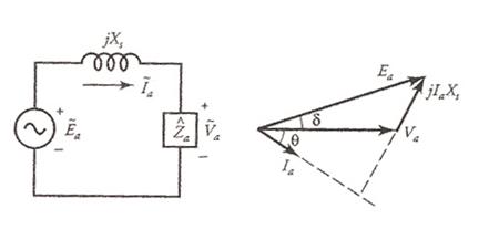
Figure 19 An approximate equivalent circuit of a synchronous generator and its phasor diagram for a lagging pf load.
The per-phase terminal voltage is
![]()
or
Thus,
Hence, the approximate power output of the generator is
 (35)
(35)
When a synchronous generator operates at a constant
speed with a constant field current, Xs
and Ea are both constants.
Va is the terminal
voltage, which is usually held constant. Thus, the power output of the
generator varies as sin d where d is the angle from ![]() to
to ![]() and is called the power
angle.
and is called the power
angle.
Equation (35) is known as the power-angle relation. This relation is also shown in the power-angle curve of Figure 20. In the development of Eq. (35) we have tacitly assumed a round rotor. For a salient-pole rotor, the curve is somewhat modified and is indicated by the dashed curve. Later in this chapter, we will develop a relationship between the power-angle and the power output for salient-pole rotors.
For a given amount of field current and a certain terminal voltage, the maximum power output Pom (or developed Pdm) of a synchronous generator is
 (36)
(36)
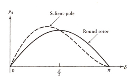
Figure 20 Power developed as a function of power-angle for a cylindrical rotor (solid) and a salient-pole rotor (dashed).
The torque developed, from Eq. (35), is
 (37)
(37)
Since the torque developed is also proportional to sin d, the angle d is also referred to as the torque angle. The torque developed by a synchronous generator opposes the torque applied by the prime mover.
The maximum torque developed by the synchronous generator, from Eq. (36), is
 (38)
(38)
10 Synchronous Generator Tests
To obtain the parameters of a synchronous generator, we perform three simple tests as described below.
The Resistance Test
This test is conducted to measure-winding resistance of a synchronous generator when it is at rest and the field winding is open. The resistance is measured between two lines at a time and the average of the three resistance readings is taken to be the measured value of the resistance, RL, from line to line. If the generator is Y-connected, the per-phase resistance is
 (39a)
(39a)
However, for a D-connected generator, the per-phase resistance is
(39b)
The Open-Circuit Test
The open-circuit test, or the no-load test, is performed by driving the generator at its rated speed while the armature winding is left open. The field current is varied in suitable steps, and the corresponding values of the open-circuit voltage between any two pair of terminals of the armature windings are recorded as depicted in Figure 21 for a Y-connected generator.
The field current can be raised until the open-circuit voltage is twice the rated value. From the recorded data for the open-circuit voltage we can compute the per-phase (open-circuit) voltage. When the per-phase (open-circuit) voltage is plotted as a function of the field current, the graph is referred to as the open-circuit saturation characteristic (curve), or OCC for short.
The OCC follows a straight-line relation as long as the magnetic circuit of the synchronous generator does not saturate.
Since, in the linear region, most of the applied mmf is consumed by the air-gap, the straight line is appropriately called the air-gap line. As the saturation sets in, the OCC starts deviating from the air-gap line, as depicted in Figure 22. The OCC is taken to be the magnetization curve of the generator under load conditions.
The Short-Circuit Test
The short-circuit test provides information about the current capabilities of a synchronous generator. It is performed by driving the generator at its rated speed when the terminals of the armature winding are shorted, as shown in Figure 23 for a Y-connected generator. An ammeter is placed in series with one of the three shorted lines.
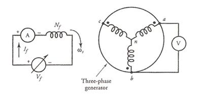
Figure 21 Circuit diagram to performs open-circuit test.
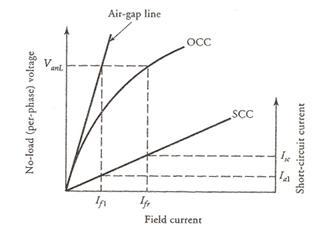
Figure 22 Open-circuit and short-circuit characteristics of a synchronous generator.
The field current is gradually increased and the corresponding value of the current is recorded. The maximum armature current under short circuit should not exceed twice the rated current of the generator. From the recorded data we can compute the per-phase short-circuit current. When the per-phase short-circuit current is plotted as a function of the field current, the graph is called the short-circuit characteristic (SCC for short) of a generator. For convenience, the OCC and SCC are plotted on the same graph, as shown in Figure 22.
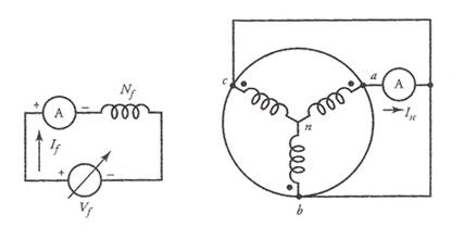
Figure 23 Circuit diagram to perform short-circuit test.
Since the terminal voltage under short-circuit condition is zero, the per-phase generated voltage must be equal to the voltage drop across the synchronous impedance. To calculate the per-phase synchronous impedance from the OCC and SCC of a synchronous generator at its rated voltage, the procedure is as follows
Find the value of the field current (Ifr) that gives the rated per-phase voltage (VanL) from the OCC of the generator.
Find the value of the short-circuit current (Isc) from the SCC for the same value of the field current, Ifr.
The magnitude of the synchronous impedance is equal to the open-circuit voltage divided by the short-circuit current. That is,
 (40)
(40)
Since the resistance of each phase winding of the armature is already known from the resistance test, the synchronous reactance of the generator is
![]() (41)
(41)
From the OCC and SCC we can, in fact, plot the synchronous impedance as a function of the field current.
A typical plot is given in Figure 24. As long as the flux density is below the knee of the saturation curve (the flux is proportional to the applied mmf), the synchronous impedance is fairly constant and is referred to as the unsaturated synchronous impedance. As the generator operates above the knee of its saturation curve, the generated voltage is smaller than what it would have been without saturation.
Consequently, the saturated synchronous impedance is smaller than its unsaturated value. Both the unsaturated and saturated synchronous impedances can be determined from Figure 22 at the rated voltage of the generator. The air-gap line gives the necessary field current If1 at the rated voltage VanL for the unsaturated synchronous impedance and the corresponding short-circuit current Ia1. Thus, the magnitude of the unsaturated synchronous impedance is
 (42)
(42)
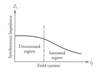
Figure 24 Synchronous impedance as a function of the field current.
and the magnitude of the (saturated) synchronous impedance has already been determined in Eq. (40).
It must, therefore, be evident that the synchronous impedance of a synchronous generator may vary considerably from light load to full load. For our calculations, we assume that Zs is constant and its value corresponds to the rated no-load voltage.
|
Politica de confidentialitate | Termeni si conditii de utilizare |

Vizualizari: 9270
Importanta: ![]()
Termeni si conditii de utilizare | Contact
© SCRIGROUP 2025 . All rights reserved