| CATEGORII DOCUMENTE |
| Bulgara | Ceha slovaca | Croata | Engleza | Estona | Finlandeza | Franceza |
| Germana | Italiana | Letona | Lituaniana | Maghiara | Olandeza | Poloneza |
| Sarba | Slovena | Spaniola | Suedeza | Turca | Ucraineana |
Definition of Crack Tip Opening Displacement
There are two common definitions of the crack tip opening displacement (CTOD):
1. The opening displacement of the original crack tip.
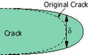
2. The displacement at the intersection of a 90 vertex with the crack flanks.
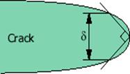
These two definitions are equivalent if the crack blunts in a semicircle.
CTOD in Specimen
The crack tip opening displacement (CTOD) of a crack at the edge of a three-point bending specimen is shown below:
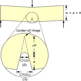
where CTODm is the measured crack tip opening displacement, usually near the edge of the specimen for ease of access, CTOD is the real crack tip opening displacement, a is the length of the crack, and b is the width of the rest of the specimen. Please note that the figure is for illustration purpose only and not to scale. From simple geometry of two similar triangles:

where ![]() is
a dimensionless rotational factor used to locate the center of the hinge.
is
a dimensionless rotational factor used to locate the center of the hinge.
For
simplicity, let's assume that the center of the hinge locates at the center of b,
i.e., ![]() ~
1/2. The CTOD then becomes
~
1/2. The CTOD then becomes

The above hinge model may not be accurate when the displacement is mostly elastic. A more accurate approach is to separate the CTOD into an elastic part and a plastic part:

where ![]() is
the small scale yielding stress and m is a dimensionless constant that
depends on the material properties and the stress states.
is
the small scale yielding stress and m is a dimensionless constant that
depends on the material properties and the stress states.
Relationship between J and CTOD
Consider a linear elastic body containing a crack, the J integral and the crack tip opening displacement (CTOD) have the following relationship

where ![]() and
m are defined in the previous section. For plane stress and nonhardening
materials, m = 1. Hence, for a through crack in an infinite
plate subjected to a remote tensile stress
and
m are defined in the previous section. For plane stress and nonhardening
materials, m = 1. Hence, for a through crack in an infinite
plate subjected to a remote tensile stress ![]() (Mode
I), the crack tip opening displacement
(Mode
I), the crack tip opening displacement ![]() is
is

Shih, C. F., 1981, took a step further and showed that a unique relationship exists between J and CTOD beyond the validity limits of LEFM. He introduced the 90 intercept definition of CTOD, as illustrated below.
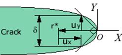
The displacement field is

The
CTOD is evaluated from ux and uy at r
= r* and ![]() :
:

Since

The CTOD becomes

Definition of J Integral
Consider a nonlinear elastic body containing a crack,
the J integral is defined as
![]()
where ![]() is
the strain energy density,
is
the strain energy density, ![]() is
the traction vector,
is
the traction vector, ![]() is
an arbitrary contour around the tip of the crack, n is the unit vector
normal to
is
an arbitrary contour around the tip of the crack, n is the unit vector
normal to ![]() ;
;
![]() ,
,
![]() ,
and u are the stress, strain, and displacement field, respectively.
,
and u are the stress, strain, and displacement field, respectively.
Rice, J. R., 1968, showed that the J integral is a path-independent line integral and it represents the strain energy release rate of nonlinear elastic materials
![]()
where ![]() is
the potential energy, the strain energy U stored in the body minus the
work W done by external forces and A is the crack area.
is
the potential energy, the strain energy U stored in the body minus the
work W done by external forces and A is the crack area.
The dimension of J is
![]()
J vs. ![]() and
K
and
K
For linear elastic materials, the
J integral J is in fact the strain energy release rate,
![]() ,
and both are related to the stress
intensity factor K in the following fashion:
,
and both are related to the stress
intensity factor K in the following fashion:
|
Politica de confidentialitate | Termeni si conditii de utilizare |

Vizualizari: 1939
Importanta: ![]()
Termeni si conditii de utilizare | Contact
© SCRIGROUP 2026 . All rights reserved